G 230 / G 240 Schematics, Machines with Basler Controller
wc_tx003749gb_FM10.fm
221
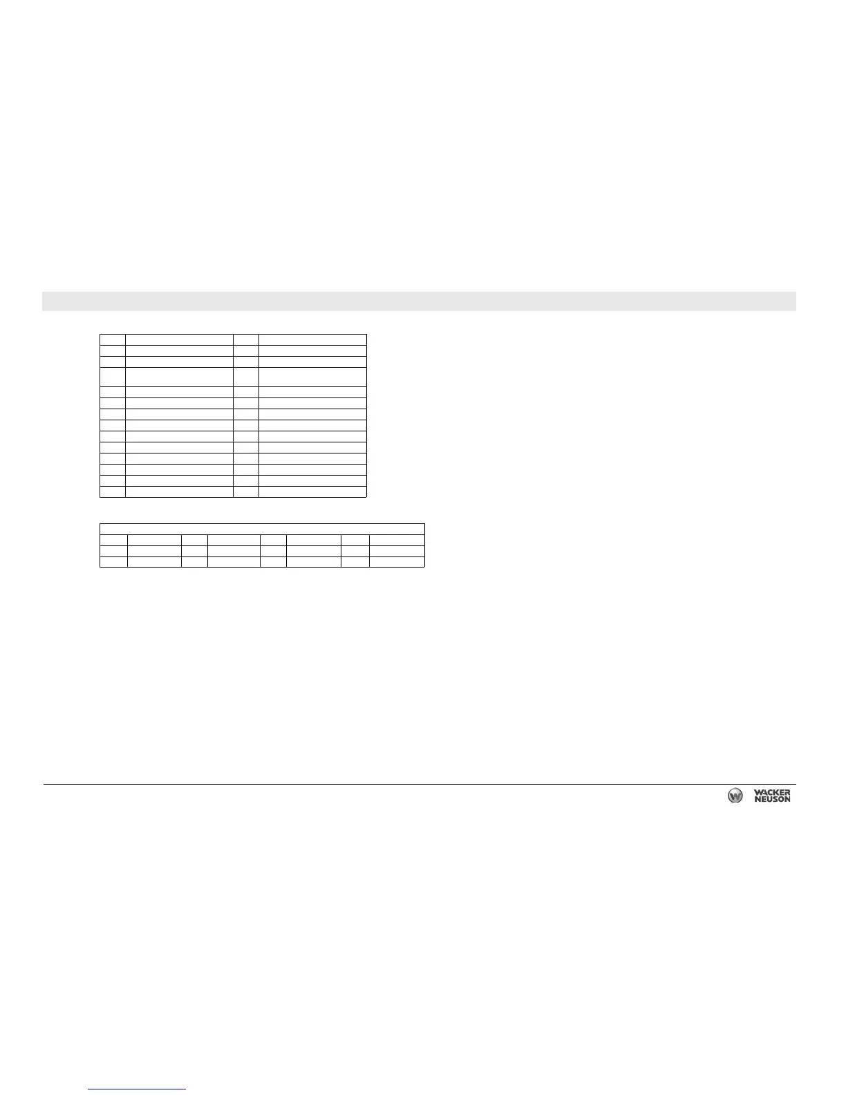
26.2 AC Schematic Components:
G 230/G 240
Ref. Description Ref. Description
1 Genset controller 14 Exciter
2 Plug 4—line voltage inputs 15 Rectifier
3 Plug 3—current transformer
inputs
16 Rotor main field
4 Voltage selector switch 17 Generator (alternator)
5 Main breaker 18 Stator auxiliary winding
6 Lug safety limit switch 19 Stator main windings
7 Mechanical lugs 20 Receptacle, 240V 50A
8 GFI receptacle, 120V 21 Exciter rotor windings
9 Circuit breaker, 120V 20A 22 Rotor
10 Circuit breaker, 240V 50A 23 Bond bar
11 Voltage adjusting rheostat 24 Shunt
12 Voltage regulator 25 Machine and components
13 Stator — —
Wire Colors
BLK Black RED Red WHT White ORG Orange
GRN Green TAN Tan YEL Yellow — —
BLU Blue VIO Violet GRY Gray — —