G 230 / G 240 Schematics, Machines with Deep Sea Controller
wc_tx003750gb_FM10.fm
239
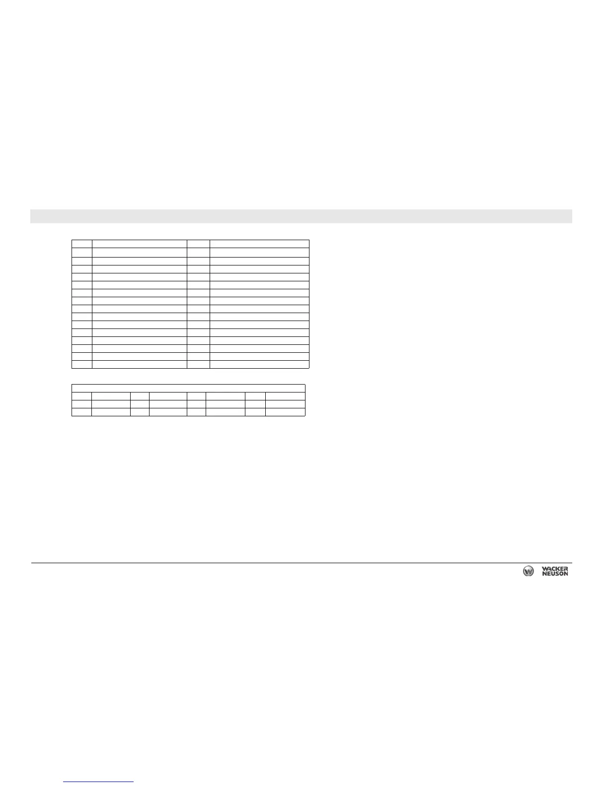
27.4 DC Schematic Components: G 240 John Deere Tier 3
Ref. Description Ref. Description
1
Plug 1 - power and engine sender inputs
16 Engine Control Unit (ECU)
2 Plug 2 - contact inputs 17 Starter relay
3 Plug 3 - CANBUS 18 Emergency stop switch
4 Electronic control unit (genset controller) 19 Remote start terminals
5 Shunt 20 Battery
6 Plug 4 - E-stop, contact outputs 21 Starter motor
7 120 ohm resistor (if equipped) 22 Alternator
8 Hour meter 23 Mechanical lugs
9 Terminal strip 24 Main circuit breaker
10 10A fuse 25 Fuel level sender
11 Battery disconnect (optional) 26 Lug door interlock switch
12 Shunt trip relay 27 Bond bar
13 7.5A fuse 28 Resistor
14 Intake heater 29 ON/OFF toggle switch
15 Heater relay 30 —
Wire Colors
BLK Black RED Red WHT White ORG Orange
GRN Green TAN Tan YEL Yellow — —
BLU Blue VIO Violet GRY Gray — —