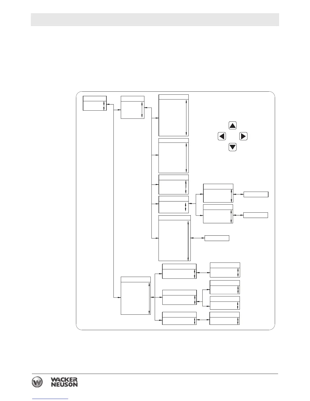
METERING and SETTINGS. Access to the METERING menu and to the
SETTINGS menu is done through the MAIN MENU. To access the MAIN MENU
button.
.
Main MenuMain Menu
MeteringMetering
SettingsSettings
MeteringMetering
EngineEngine
GeneratorGenerator
PowerPower
Run StatisticsRun Statistics
Alarm-StatusAlarm-Status
EngineEngine
Oil PressureOil Pressure
Coolant TempCoolant Temp
Battery VoltBattery Volt
RPMRPM
Speed SourceSpeed Source
Fuel LevelFuel Level
Engine LoadEngine Load
Coolant Level*Coolant Level*
Total Run TimeTotal Run Time
Hrs to MaintenanceHrs to Maintenance
DEF Tank Level*DEF Tank Level*
SettingsSettings
General SettingsGeneral Settings
CommunicationsCommunications
Sys ParametersSys Parameters
Programmable InputsProgrammable Inputs
Alarm ConfigAlarm Config
Generator ProtectionGenerator Protection
Breaker ManagementBreaker Management
Bias ControlBias Control
Enter PasswordEnter Password
General SettingsGeneral Settings
Front Panel HMIFront Panel HMI
Configure Date/TimeConfigure Date/Time
Alarm ConfigurationAlarm Configuration
AlarmsAlarms
System ParametersSystem Parameters
System SettingsSystem Settings
Crank SettingsCrank Settings
Alarm-StatusAlarm-Status
AlarmsAlarms
Pre-AlarmsPre-Alarms
StatusStatus
InputsInputs
OutputsOutputs
Conf ElementsConf Elements
Conf Prot StatusConf Prot Status
Event LogEvent Log
J1939 Data*J1939 Data*
J1939 Engine Config*J1939 Engine Config*
J1939 Active DTC*J1939 Active DTC*
J1939 Previous DTC*J1939 Previous DTC*
Run StatisticsRun Statistics
CumulativeCumulative
SessionSession
PowerPower
kW kW
kVAkVA
kVARkVAR
PF PF
GeneratorGenerator
Voltages Voltages
FrequencyFrequency
AmpsAmps
Bus VBus V
Bus FrequencyBus Frequency
SynchronizerSynchronizer
Max Vector ShiftMax Vector Shift
Max ROCOFMax ROCOF
ROCOFROCOF
SessionSession
Session InfoSession Info
Total Run TimeTotal Run Time
Loaded Run TimeLoaded Run Time
Unloaded Run TimeUnloaded Run Time
System SettingsSystem Settings
System UnitsSystem Units
Maintenance ResetMaintenance Reset
CumulativeCumulative
Cumulative InfoCumulative Info
Total Run TimeTotal Run Time
Loaded Run TimeLoaded Run Time
Unloaded Run TimeUnloaded Run Time
Front Panel HMIFront Panel HMI
LCD ContrastLCD Contrast
LanguageLanguage
AlarmsAlarms
Low Fuel LevelLow Fuel Level
Detailed DataDetailed Data
Detailed DataDetailed Data
Detailed DataDetailed Data
* NOT AVAILABLE ON SOME MODELS* NOT AVAILABLE ON SOME MODELS
DIAGNOSTIC MENUDIAGNOSTIC MENU
NAVIGATIONNAVIGATION
UPUP
FORWARDFORWARD
BACKBACK
DOWNDOWN
Crank SettingsCrank Settings
Cooldown TimeCooldown Time
wc_gr007618