G 230 / G 240 Schematics, Machines with Basler Controller
wc_tx003749gb_FM10.fm
225
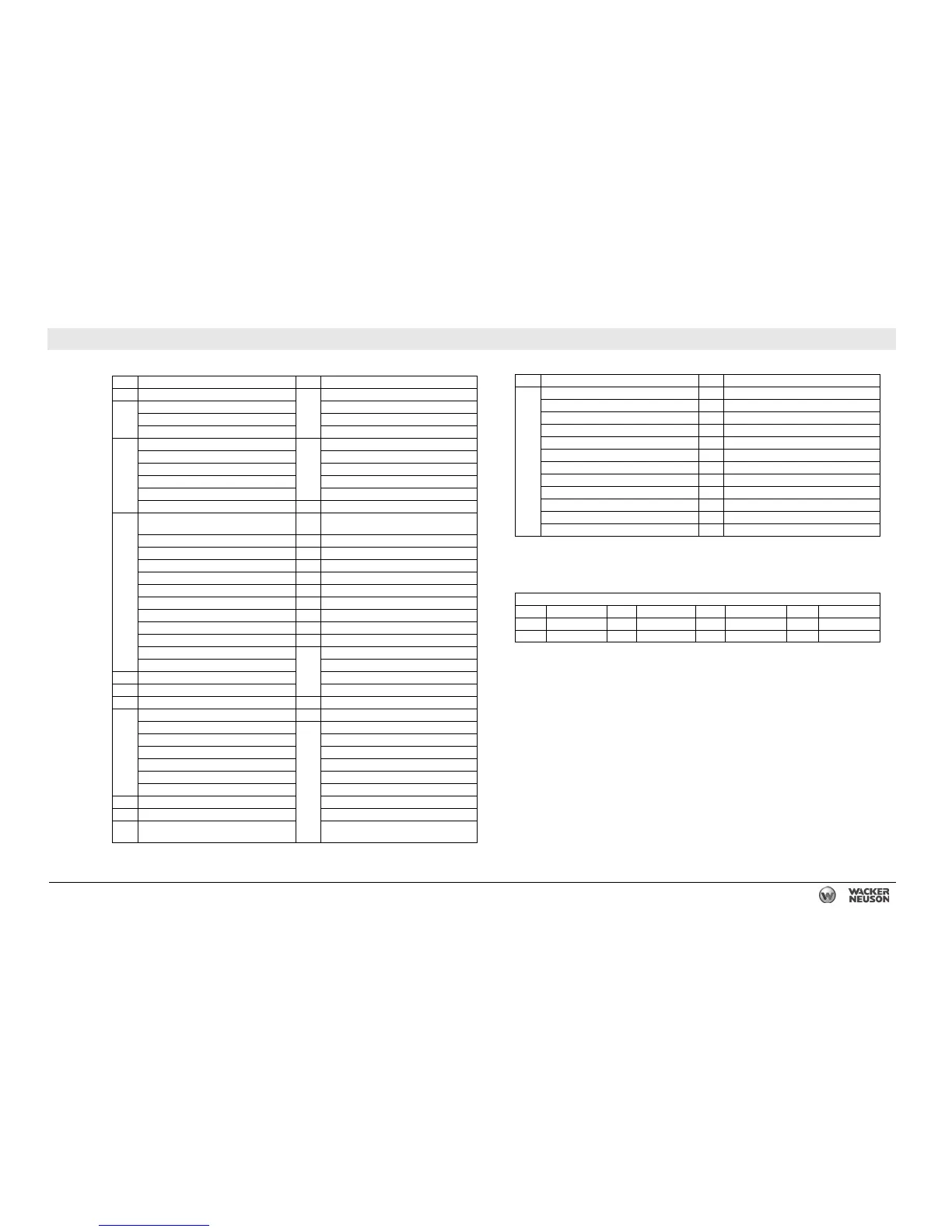
26.6 DC Schematic Components: G 230 T4i
Ref. Description Ref. Description
1 Electronic control board 13 Cummins J3 connector
2 Engine outputs B: J1939 (–)
Start A: J1939 (+)
Fuel C: Shield
3 Plug 1—Engine sensor inputs 14 Cummins C12 connector
1: Ground 1: Pressure
2: Battery (–) 2: Sensor supply
3: Battery (+) 3: Temperature
9: Fuel Level 4: Sensor return
11: Sender com 15 Remote start
4 Plug 4—Emergency stop, canbus, and
contact outputs
16 Emergency stop switch
46: Emergency stop 17 Toggle switch
47: Emergency stop 18 Bond bar
48: Canbus L 19 Main breaker
49: Canbus H 20 Lug door safety switch
50: Shield 21 Mechanical lugs
51: Remote annunciator common 22 Intake heater relay (if equipped)
52: Alarm 23 Intake heater (if equipped)
53: Pre-alarm 24 Starter relay
54: Regeneration light 25 Starter
55: Battery (+) 26 Cummins C7 connector
56: Trip breaker 1: Sensor supply
5 Fuses 2: Signal
6 Hour meter 3: Sensor return
7 Shunt trip relay 27 12V battery
8 Plug 2—Contact inputs 28 Battery disconnect switch (if equipped)
18: Regeneration 29 21 pin Cummins after treatment connector
21: Idle 3: OEM sensor return
27: Remote start 4: Diesel particulate filter pressure change
28: Remote start mode 5: Diesel particulate filter out pressure
29: Run mode 2: OEM sensor supply
30: Breaker (tripped) 7: DOC outlet temperature
9 Light 1: Temperature return
10 Start relay 8: DOC inlet temperature
11 150A fuse 9: Diesel particulate filter outlet
temperature
12 16 pin Cummins OEM connector 30 Air cleaner TBAP sensor
A: 24V (+) ECM power 31 Terminal block
F: 24V (+) service link 32 Resistor (if equipped)
H: Keyswitch 33 Coolant level sensor
E: Starter solenoid 34 DPF pressure sensor connector
B: Throttle input 35 DPF temperature sensor connector
Fan speed signal 36 Fuel level
P: Fan speed return 37 7.5A fuse
S: Air heater return 38 1A fuse
R: Air heater signal 39 5A fuse
J: 24V (–) ECM power — —
K: Data link return — —
Wire Colors
BLK Black RED Red WHT White ORG Orange
GRN Green TAN Tan YEL Yellow — —
BLU Blue VIO Violet GRY Gray — —
Ref. Description Ref. Description