G 230 / G 240 Schematics, Machines with Deep Sea Controller
wc_tx003750gb_FM10.fm
247
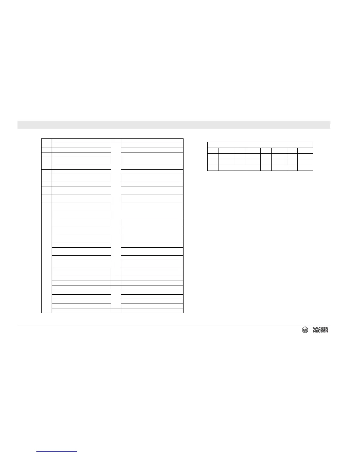
27.12 Electrical Schematic Components
Ref. Description Ref. Description
14 Intake heater Coolant sensor return
15 Intake heater relay Coolant sensor signal
16 150A Fuse Sensor (+5V) supply
17
Starter relay Diesel Exhaust Fluid (DEF) supply module
pump mode/temperature driver
20 Battery Diesel Exhaust Fluid (DEF) pressure sensor
21 Starter motor Diesel Exhaust Fluid (DEF) pump motor return
29
Battery disconnect switch (not used on
some models)
Diesel Exhaust Fluid (DEF) pump motor
supply
30 120 Ohm resistor Diesel Exhaust Fluid (DEF) reverting valve
31
Coolant level sensor Diesel Exhaust Fluid (DEF) pressure line
heater diagnostic
47
Cummins Engine Control Unit (ECU)
connector
Diesel Exhaust Fluid (DEF) backflow line
heater diagnostic
Water in fuel sensor Diesel Exhaust Fluid (DEF) suction line heater
diagnostic
ECM return Diesel Exhaust Fluid (DEF) line heaters relay
control
Battery supply positive Diesel Exhaust Fluid (DEF) line heater current
monitor (1 of 2)
Battery supply positive Diesel Exhaust Fluid (DEF) line heater current
monitor (2 of 2)
Battery supply positive Diesel Exhaust Fluid (DEF) supply module
relay control
Battery supply positive Diesel Exhaust Fluid (DEF) dosing injector low
Battery supply positive Diesel Exhaust Fluid (DEF) dosing injector
high
Key switch (Not used)
Intake air relay return Diesel Exhaust Fluid (DEF) tank heating valve
return
Intake air relay signal Diesel Exhaust Fluid (DEF) tank heating valve
supply
Battery supply negative 48 Cummins water in fuel sensor
Battery supply negative 52 Cummins diagnostic connector
Battery supply negative Datalink return
Battery supply negative +24V Datalink
Battery supply negative J1939+
J1939- J1939-
J1939+ Shield
(Not used) — —
Wire Colors
BK Black RD Red YL Yellow OR Orange
GN Green TN Tan BR Brown PU Purple
BU Blue VIO Violet CL Clear SH Shield
PK Pink WH White GY Gray LB Lt. blue