G 230 / G 240 Schematics, Machines with Basler Controller
wc_tx003749gb_FM10.fm
223
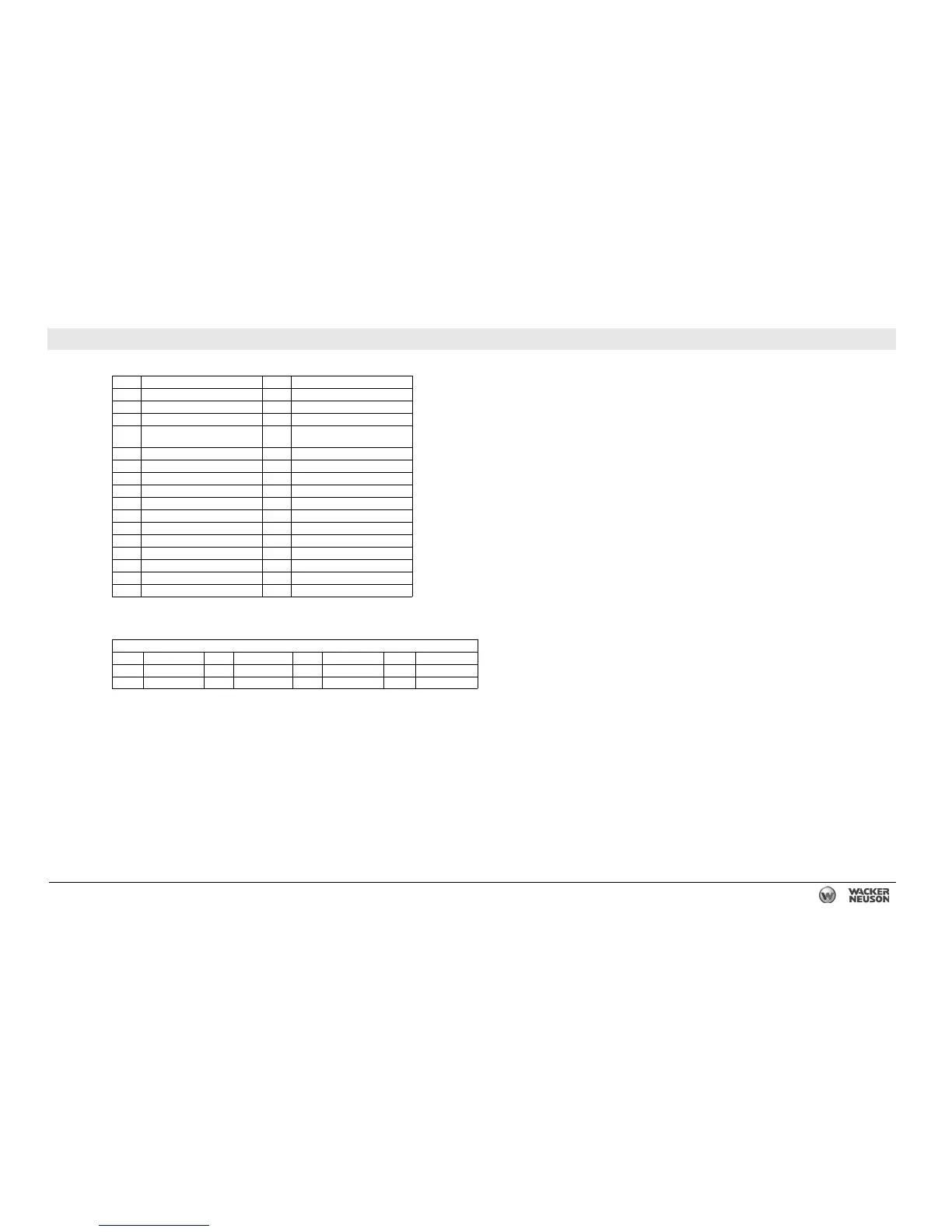
26.4 DC Schematic Components: G 240 Tier 3
Ref. Description Ref. Description
1 Electronic control board 17 Toggle switch
2 Engine outputs 18 10A fuse
3 Engine sensor inputs 19 Main breaker
4 Emergency stop, canbus, and
contact outputs
20 Lug door safety switch
5 Fuses 21 Mechanical lugs
6 Hour meter 22 Relay (if equipped)
7 Shunt trip relay 23 Intake heater (if equipped)
8 Contact inputs 24 Starter relay
9 21 position connector 25 Starter
10 Start relay 26 Alternator
11 Alternator / charge 27 12V battery
12 B+ switched 28 Battery disconnect switch
13 Crank delay 29 John Deere engine ECU
14 Fuel level 30 Engine harness
15 Remote start 31 Terminal block
16 Emergency stop switch 32 Resistor (if equipped)
Wire Colors
BLK Black RED Red WHT White ORG Orange
GRN Green TAN Tan YEL Yellow — —
BLU Blue VIO Violet GRY Gray — —