wc_tx003617gb_FM10.fm
53
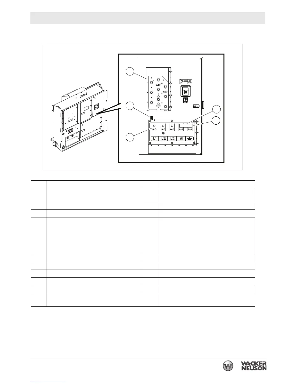
Operation, Control, and Component Locations
Ref. Description Ref. Description
a Main circuit breaker n GFI receptacle
(120 VAC, 20 Amp)
b Voltage adjustment rheostat o Remote run terminal block
c Hour meter p Emergency stop switch
d (If equipped)
Diesel Particulate Filter (DPF) switch and
indicator
or
Manual conditioning switch for
aftertreatment exhaust system
q Interlock switch (lug panel door switch)
e Genset controller (Basler or Deep Sea) r Customer connection terminal lugs
f Engine start switch or genset power switch s Ground connection
h Circuit breaker (240V, 50 Amp) t Bond bar
j Idle switch (high and low) (if equipped) u Customer connection terminal lugs door
k Circuit breaker (120V, 20 Amp) v Voltage selector access door
m Twist-lock receptacle
(120/240 VAC, 50 Amp)
w Voltage selector switch