Watlow PM PLUS™ 6 • 21 • Chapter 2: Installation
Wiring Notes
Maximum wire size
termination and torque
rating:
0.0507 to 3.30 mm2 (30
to 12 AWG) single-wire
termination or two 1.31
mm2 (16 AWG)
0.56 Nm (5.0 in-lb.)
torque
Adjacent terminals may
be labeled differently
depending on the model
number.
Do not connect wires to
unused terminals.
Maintain electrical isola-
tion between analog
input 1, digital input-
outputs, switched dc/
open collector outputs
and process outputs to
prevent ground loops.
This equipment is suit-
able for use in CLASS I,
DIVISION 2, Groups A,
B, C and D or Non-Haz-
ardous locations only.
Temperature Code T4A
Wiring Warnings
ç
Use National Electric
(NEC) or other country-
specic standard wiring
and safety practices
when wiring this control-
ler to a power source,
electrical sensors or pe-
ripheral devices. Failure
to do so may result in
damage to equipment
and property, and/or in-
jury or loss of life.
Explosion Hazard - Dry
contact closure Digital
Inputs shall not be used
in Class I Division 2 Haz-
ardous Locations unless
switch used is approved
for this application.
Explosion Hazard – Sub-
stitution of component
may impair suitability for
CLASS I, DIVISION 2.
Explosion Hazard - Do
not disconnect while the
circuit is live or unless
the area is known to be
free of ignitable concen-
trations of ammable
substances.
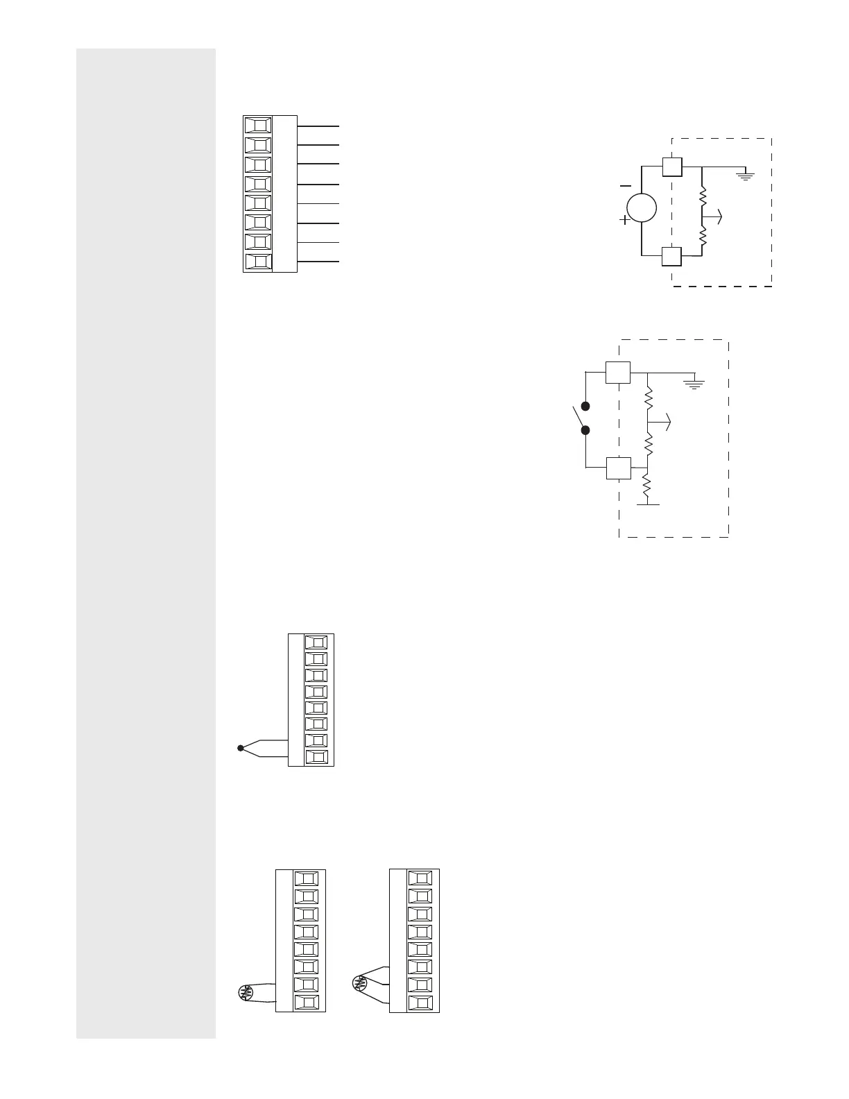
Digital Input 5 - 6
PM _ _ [2,4] _ _ - _ _ _ _ _ _ _
98
99
CF
CD
CE
B5
D6
D5
Slot C
DC Input
common
DC Input
Digital Input
• Update rate 10 Hz
• Dry contact or dc voltage
DC Voltage
• Input not to exceed 36V (dc) at
3mA
• Input active when > 3V (dc) @
0.25mA
• Input inactive when < 2V
Dry Contact
• Input inactive when > 500Ω
• Input active when < 100Ω
• Maximum short circuit 13mA
Voltage Input
common
Vdc
D
_
B
_
Dry Contact
common
24 Vdc
B
_
_
D
Input 1, 2 Thermocouple
Input 1: PM _ [C,R] _ _ _ - _ _ _ _ _ _ _ (S1/R1)
Input 2: PM _ _ _ _ _ - _ [C,R,L] _ _ _ _ _ (S2/R2)
-
+
S_
R_
Slot A,B
• 2kΩ maximum source resistance
• >20MΩ input impedance
• 3µA open-sensor detection
• Thermocouples are polarity sensitive. The negative lead (usually red)
must be connected to S1 and/or S2.
• To reduce errors, the extension wire for thermocouples must be of the
same alloy as the thermocouple.
Input 1, 2 RTD
Input 1: PM _ [C,R,] _ _ _ - _ _ _ _ _ _ _ (S1/R1),(T1/S1/R1)
Input 2: PM _ _ _ _ _ - _ [C,R,L] _ _ _ _ _ (S2/R2), (T2/S2/R2)
S_
R_
S1
S3
Slot A,B
T_
S_
R_
S1
S2
S3
Slot A, B
• Platinum, 100 and 1kΩ @ 0°C
• Calibration to DIN curve (0.00385 Ω/Ω/°C)
• 20Ω total lead resistance
• RTD excitation current of 0.09mA typical. Each ohm of
lead resistance may affect the reading by 0.03°C.
• For 3-wire RTDs, the S1 lead (usually white) must be
connected to R1 and/or R2
• For accuracy use a 3-wire RTD to compensate for
lead-length resistance. All three lead wires must have
the same resistance
 Loading...


