Watlow PM PLUS™ 6 • 25 • Chapter 2: Installation
Wiring Notes
Maximum wire size
termination and torque
rating:
0.0507 to 3.30 mm2 (30
to 12 AWG) single-wire
termination or two 1.31
mm2 (16 AWG)
0.56 Nm (5.0 in-lb.)
torque
Adjacent terminals may
be labeled differently
depending on the model
number.
Do not connect wires to
unused terminals.
Maintain electrical isola-
tion between analog
input 1, digital input-
outputs, switched dc/
open collector outputs
and process outputs to
prevent ground loops.
This equipment is suit-
able for use in CLASS I,
DIVISION 2, Groups A,
B, C and D or Non-Haz-
ardous locations only.
Temperature Code T4A
Wiring Warnings
ç
Use National Electric
(NEC) or other country-
specic standard wiring
and safety practices
when wiring this control-
ler to a power source,
electrical sensors or pe-
ripheral devices. Failure
to do so may result in
damage to equipment
and property, and/or in-
jury or loss of life.
Explosion Hazard - Dry
contact closure Digital
Inputs shall not be used
in Class I Division 2 Haz-
ardous Locations unless
switch used is approved
for this application.
Explosion Hazard – Sub-
stitution of component
may impair suitability for
CLASS I, DIVISION 2.
Explosion Hazard - Do
not disconnect while the
circuit is live or unless
the area is known to be
free of ignitable concen-
trations of ammable
substances.
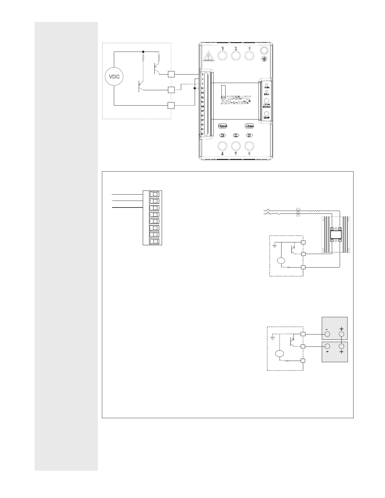
Switched DC Wiring Example Using DO 5-6
VDC
switched dc outputs
Internal Circuitry
+
+
-
-
DC80-60C0-0000
Htr 2
Htr 1
D5
D6
B5
Output 1, 3 Switched DC/Open Collector
•
dc - (open collector)
dc +
common
X_
W_
Y_
Slot A, B
Switched DC
• Maximum open circuit voltage is
22 to 25VDC
• 30mA max. per single output /
40mA max. total per paired outputs
(1 & 2, 3 & 4)
• Typical drive; 4.5V (dc) @ 30mA
• Short circuit limited to <50mA
• NPN transistor sink
• Use dc- and dc+ to drive external
solid-state relay
• 1-pole DIN-A-MITE: up to 4 in
parallel or 4 in series
• 2-pole DIN-A-MITE: up to 2 in
parallel or 2 in series
• 3-pole DIN-A-MITE: up to 2 in
series
Open Collector
• 100mA maximum output current
sink
• 30V (dc) max. supply voltage
• Any switched dc output can use the
common terminal.
• Use an external power supply to
control a dc load, with the load
positive to the positive of the power
supply, the load negative to the
open collector and common to the
power supply negative.
Switched DC
Open Collector
Load
Power Supply
dc -
common
24VDC
X
_
W
_
Y
_
Output 1: (X1,-W1,+Y1)
PM _ _ _ [C] _ - _ _ _ _ _ _ _
Output 3: (X3,-W3,+Y3)
PM _ _ _ _ _ - _ _ [C] _ _ _ _
dc +
dc -
common
24VDC
X
_
W
_
Y
_
1(–) (+)2
4(–) (+)3
(-) (+)
Switched DC
Heater
Contacts
(If Required)
L2
L1
Semiconductor
Fuse
 Loading...


