Watlow PM PLUS™ 6 • 26 • Chapter 2: Installation
Wiring Notes
Maximum wire size termi-
nation and torque rating:
0.0507 to 3.30 mm2 (30
to 12 AWG) single-wire
termination or two 1.31
mm2 (16 AWG)
0.56 Nm (5.0 in-lb.)
torque
Adjacent terminals may
be labeled differently
depending on the model
number.
Do not connect wires to
unused terminals.
Maintain electrical isola-
tion between analog
input 1, digital input-
outputs, switched dc/
open collector outputs
and process outputs to
prevent ground loops.
This equipment is suit-
able for use in CLASS
I, DIVISION 2, Groups
A, B, C and D or Non-
Hazardous locations only.
Temperature Code T4A
Wiring Warnings
ç
Use National Electric
(NEC) or other country-
specic standard wiring
and safety practices
when wiring this control-
ler to a power source,
electrical sensors or pe-
ripheral devices. Failure
to do so may result in
damage to equipment
and property, and/or in-
jury or loss of life.
Explosion Hazard - Dry
contact closure Digital
Inputs shall not be used
in Class I Division 2 Haz-
ardous Locations unless
switch used is approved
for this application.
Explosion Hazard – Sub-
stitution of component
may impair suitability for
CLASS I, DIVISION 2.
Explosion Hazard - Do
not disconnect while the
circuit is live or unless
the area is known to be
free of ignitable concen-
trations of ammable
substances.
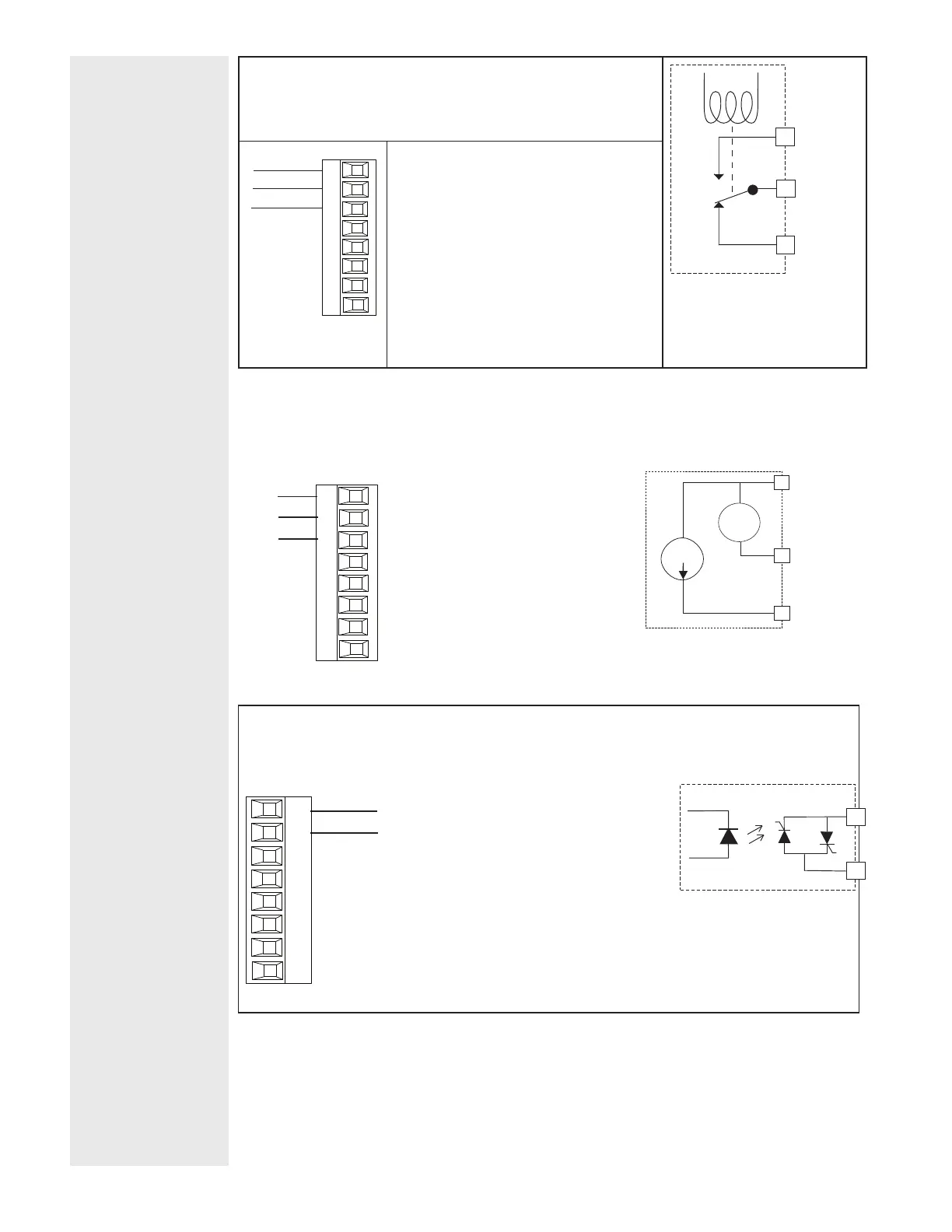
Output 1, 3 Mechanical Relay, Form C
Output 1: (L1,K1,J1 PM _ _ _ [E] _ - _ _ _ _ _ _ _
Output 3: (L3,K3,J3) PM _ _ _ _ _ - _ _ [E] _ _ _ _
normally open
common
normally closed
L
_
K
_
J
_
normally open
normally closed
common
L_
K_
J_
Slot A, B
• 5A at 240VÅ (ac) or 30VÎ (dc) maxi-
mum resistive load
• 20mA at 24V minimum load
• 125VA pilot duty at 120/240VÅ (ac),
25VA at 24VÅ (ac)
• 100,000 cycles at rated load
• Output does not supply power.
• For use with ac or dc
Output 1, 3 Universal Process
Output 1: (F1,G1,H1) PM _ _ _ [F] _ - _ _ _ _ _ _ _
Output 3: (F3,G3,H3) PM _ _ _ _ _ - _ _ [F] _ _ _ _
volts or current -
current +
volts +
F_
G_
H_
Slot A, B
• 0 to 20mA into 800 Ω maximum
load
• 0 to 10VÎ (dc) into 1 kΩ minimum
load
• Scalable
• Output supplies power
• Cannot use voltage and current
outputs at same time
• Output may be used as retransmit
or control.
negative
volts +
current +
4 to 20 mA
0 to 10 V
F
3
G
3
H3
Output 1, 3 Solid-State Relay, Form A
Output 1: (L1, K1) PM _ _ _ [K] _ - _ _ _ _ _ _ _
Output 3: (L3, K3) PM _ _ _ _ _ - _ _ [K] _ _ _ _
normally open
common
L_
K_
Slot A, B
• 0.5A at 20 to 264VÅ (ac) max resistive
load
• 20VA 120/240VÅ (ac) pilot duty
• Opto-isolated, without contact suppres-
sion
• Maximum off state leakage of 105µA
• Output does not supply power
• Minimum holding current of 10mA
• Do not use on dc loads.
• See Quencharc note
L
_
K
_
 Loading...


