Watlow PM PLUS™ 6 • 30 • Chapter 2: Installation
Wiring Notes
Maximum wire size termi-
nation and torque rating:
0.0507 to 3.30 mm2 (30
to 12 AWG) single-wire
termination or two 1.31
mm2 (16 AWG)
0.56 Nm (5.0 in-lb.)
torque
Adjacent terminals may
be labeled differently
depending on the model
number.
Do not connect wires to
unused terminals.
Maintain electrical isola-
tion between analog
input 1, digital input-
outputs, switched dc/
open collector outputs
and process outputs to
prevent ground loops.
This equipment is suit-
able for use in CLASS
I, DIVISION 2, Groups
A, B, C and D or Non-
Hazardous locations only.
Temperature Code T4A
Wiring Warnings
ç
Use National Electric
(NEC) or other country-
specic standard wiring
and safety practices
when wiring this control-
ler to a power source,
electrical sensors or pe-
ripheral devices. Failure
to do so may result in
damage to equipment
and property, and/or in-
jury or loss of life.
Explosion Hazard - Dry
contact closure Digital
Inputs shall not be used
in Class I Division 2 Haz-
ardous Locations unless
switch used is approved
for this application.
Explosion Hazard – Sub-
stitution of component
may impair suitability for
CLASS I, DIVISION 2.
Explosion Hazard - Do
not disconnect while the
circuit is live or unless
the area is known to be
free of ignitable concen-
trations of ammable
substances.
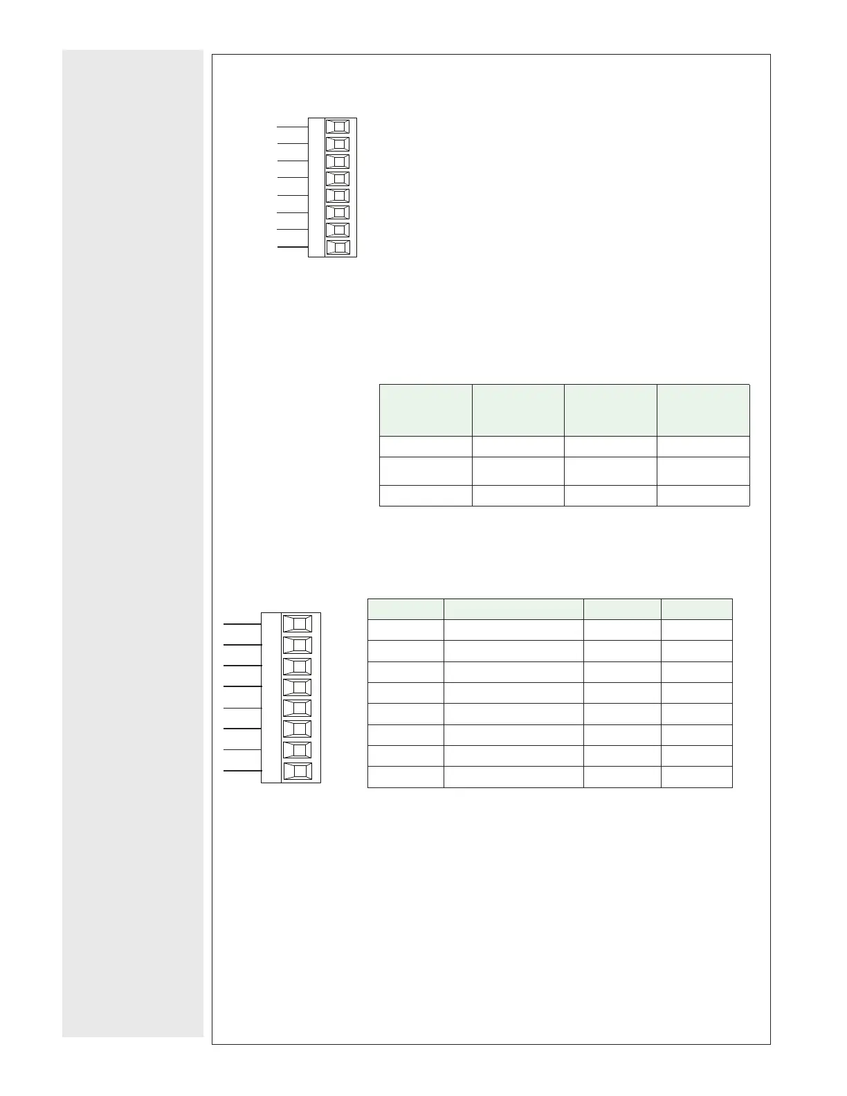
EIA-232/485 Modbus
®
RTU Communications
PM [6] _ _ _ _ - [2] _ _ _ _ _ _
485 common
485 T+/R+
CB
CA
CC
CB
CA
C5
C3
C2
Slot B, E
485 T-/R-
485 T+/R+
485 T-/R-
232 common
232 (TX) to DB9 pin 2 (RD)
232 (RD) to DB9 pin 3 (TX)
• Wire T-/R- to the A terminal of the EIA-485 port.
• Wire T+/R+ to the B terminal of the EIA-485 port.
• Wire common to the common terminal of the EIA-485 port.
• Do not route network wires with power wires. Connect network wires
in daisy-chain fashion when connecting multiple devices in a network.
• A termination resistor may be required. Place a 120 Ω resistor across
T+/R+ and T-/R- of last controller on network.
• Do not wire to both the EIA-485 and the EIA-232 pins at the same
time.
• Two EIA-485 terminals of T/R are provided to assist in daisy-chain
wiring.
• Do not connect more than one controller on an EIA-232 network.
• Maximum number of controllers on a Modbus
®
network is 247.
• Maximum EIA-232 network length: 15 meters (50 feet)
• Maximum EIA-485 network length: 1,200 meters (4,000 feet)
• 1/8th unit load on EIA-485 bus.
• Communications instance 2
Modbus
®
-
IDA Termi-
nal
EIA/TIA-485
Name
Watlow Ter-
minal Label
Function
DO A CA or CD T-/R-
D1 B CB or CE T+/R+
common common CC or CF common
EtherNet/IP™, PCCC, and Modbus
®
TCP Communications
(Instance 2)
Slot B: PM [6] _ _ _ _ - [3] _ _ _ _ _ _
receive -
unused
E8
E7
E6
E5
E4
E3
E2
E1
Slot B, E
unused
unused
unused
receive +
transmit -
transmit +
RJ-45 pin T568B wire color Signal Slot B
8 brown unused E8
7 brown & white unused E7
6 green receive - E6
5 white & blue unused E5
4 blue unused E4
3 white & green receive + E3
2 orange transmit - E2
1 white & orange transmit + E1
• Do not route network wires with power wires.
• Connect one Ethernet cable per controller to a 10/100 Mbps Ethernet
switch. Both Modbus
®
TCP and EtherNet/IP™ are available on the net-
work.
• When using Modbus
®
TCP, the Network Status and Module Status LEDs
are not used.
 Loading...


