Watlow PM PLUS™ 6 • 29 • Chapter 2: Installation
Wiring Notes
Maximum wire size
termination and torque
rating:
0.0507 to 3.30 mm2 (30
to 12 AWG) single-wire
termination or two 1.31
mm2 (16 AWG)
0.56 Nm (5.0 in-lb.)
torque
Adjacent terminals may
be labeled differently
depending on the model
number.
Do not connect wires to
unused terminals.
Maintain electrical isola-
tion between analog
input 1, digital input-
outputs, switched dc/
open collector outputs
and process outputs to
prevent ground loops.
This equipment is suit-
able for use in CLASS I,
DIVISION 2, Groups A,
B, C and D or Non-Haz-
ardous locations only.
Temperature Code T4A
Wiring Warnings
ç
Use National Electric
(NEC) or other country-
specic standard wiring
and safety practices
when wiring this control-
ler to a power source,
electrical sensors or pe-
ripheral devices. Failure
to do so may result in
damage to equipment
and property, and/or in-
jury or loss of life.
Explosion Hazard - Dry
contact closure Digital
Inputs shall not be used
in Class I Division 2 Haz-
ardous Locations unless
switch used is approved
for this application.
Explosion Hazard – Sub-
stitution of component
may impair suitability for
CLASS I, DIVISION 2.
Explosion Hazard - Do
not disconnect while the
circuit is live or unless
the area is known to be
free of ignitable concen-
trations of ammable
substances.
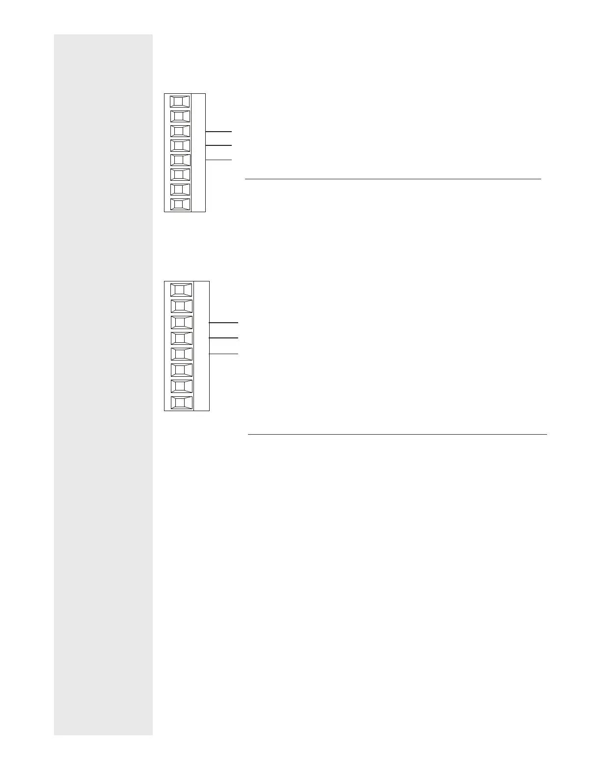
Standard Bus EIA-485 Communications
PM _ _ _ _ _ - [*] _ _ _ _ _ _
*All models include Standard Bus communications (instance 1)
T-/R-
common
98
99
CF
CD
CE
B5
D6
D5
Slot C
T+/R+
• Wire T-/R- to the A terminal of the EIA-485 port.
• Wire T+/R+ to the B terminal of the EIA-485 port.
• Wire common to the common terminal of the EIA-485 port.
• Do not route network wires with power wires. Connect network wires in
daisy-chain fashion when connecting multiple devices in a network.
• Do not connect more than 16 controllers on a network.
• Maximum network length: 1,200 meters (4,000 feet)
• 1/8th unit load on EIA-485 bus
Note: Do not leave a USB to EIA-485 converter connected to Standard Bus with-
out power (i.e., disconnecting the USB end from the PC and leave the converter
connected on Standard Bus). Disturbance on the Standard Bus may occur.
Modbus
®
RTU or Standard Bus EIA-485 Communications
PM _ _ _ _ - [1] _ _ _ _ _ _
T-/R-
common
98
99
CC
CA
CB
B5
D6
D5
Slot C
T+/R+
• Wire T-/R- to the A terminal of the EIA-485 port.
• Wire T+/R+ to the B terminal of the EIA-485 port.
• Wire common to the common terminal of the EIA-485 port.
• Do not route network wires with power wires. Connect network wires in
daisy-chain fashion when connecting multiple devices in a network.
• A termination resistor may be required. Place a 120 Ω resistor across T+/
R+ and T-/R- of last controller on network.
• Only one protocol per port is available at a time: either Modbus
®
RTU or
Standard Bus.
• Do not connect more than 16 controllers on a Standard Bus network.
• Maximum number of controllers on a Modbus
®
network is 247.
• Maximum network length: 1,200 meters (4,000 feet)
• 1/8th unit load on EIA-485 bus.
• Communications instance 1
Note: Do not leave a USB to EIA-485 converter connected to Standard Bus with-
out power (i.e., disconnecting the USB end from the computer while leaving the
converter connected on Standard Bus). Disturbance on the Standard Bus may
occur.
 Loading...


