57
CHAPTER 6 - DETAILED PARAMETER DESCRIPTION
NOTE!
DIs ON (status 1) when connected to 0 V (XC1:5).
When F* < 0 one takes the module of F* and reverses the direction
of rotation (if this is possible - P231 = 2 and if the selected control
is not forward run/reverse run.
Keypad
Reference
(P121)
P124 to P131
P265 = 7/8
P266 = 7/8
MULTISPEED
DI4
DI3
DI2
1
2
3
4
5
6
7
8
9
10
11
12
6 - Multispeed
0 - Keypad
Frequency Reference
Selection
P221 or P222
F*
P131
P130
P129
P128
P127
P126
P125
P124
000 001 010 011 100 101 110 111
0 V
HMI
DI1
P263 = 7/8
P264 = 7/8
Accel.
Enable Function
Dec el.
Inverter
Desabled
ELETRONIC POTENTIOMETER (EP)
4 to 20 mA
AI1
P235
P234
P134
P236
1 - AI1
Digital
References
Analog
References
100 %
P235 = 0
P235 = 1
0
2 V/4 mA 10 V/20 mA
Reset
0 to 10 V
+10 V
0 V
P263 to P266 = 16/18
P263 to P266 = 17/19
P271
7 - Input
Frequency
3 - HMI
Potentiometer
HMI
Potentiometer
Reference
2 - EP
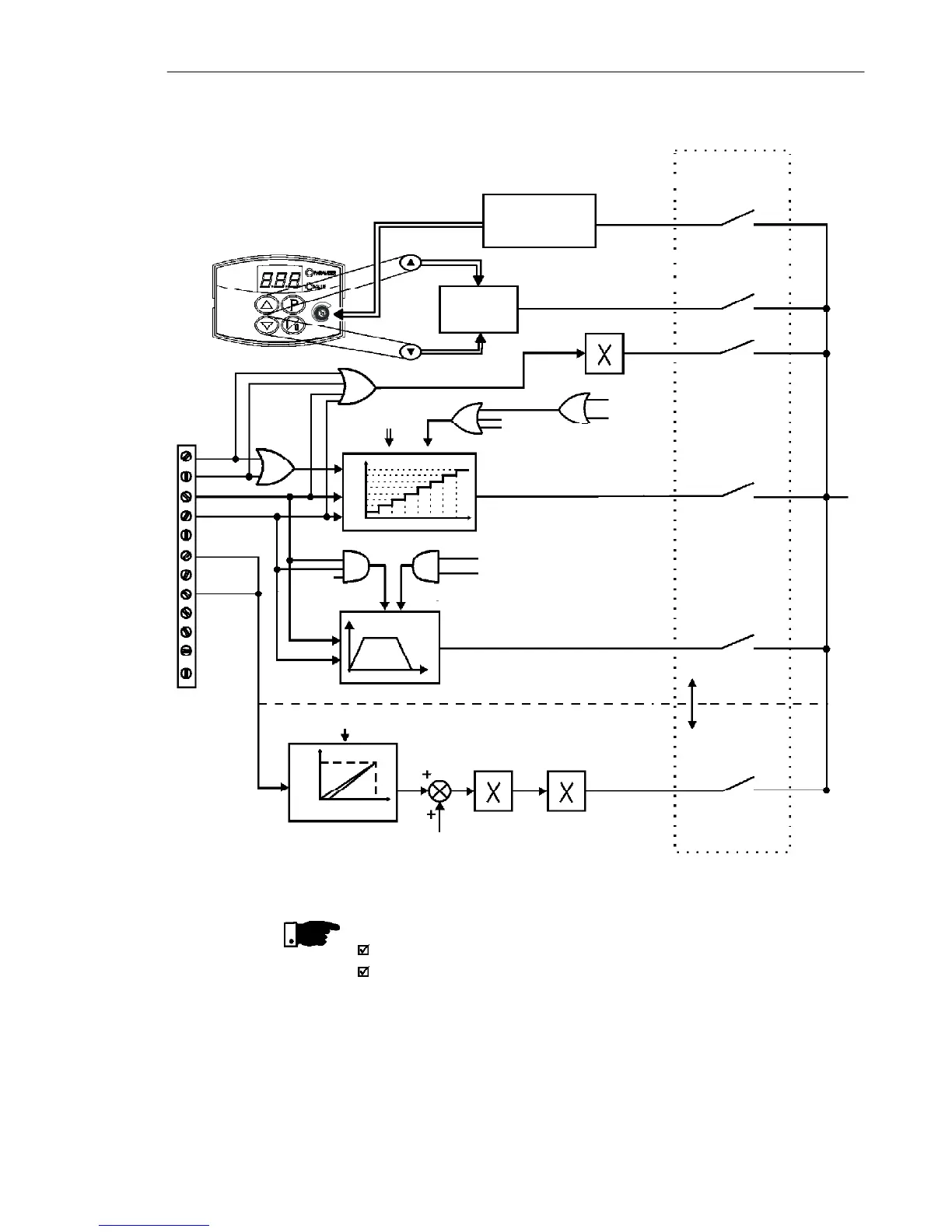
Figure 6.1 - Block diagram of the frequency reference