69
CHAPTER 6 - DETAILED PARAMETER DESCRIPTION
Range
[Factory Setting]
Parameter Description / Notes
P142
(1)(2)
0 to 100
Maximum Output [ 100 ]
Voltage 0.1 %
P145
(1)(2)
P133 to P134
Field Weakening [ 60.0 Hz ]
Frequency 0.01 Hz (< 100 Hz)
(Rated 1 Hz (> 99.9 Hz)
Frequency)
Define the V/F curve used in V/Fcontrol (P202 = 0 or 1).
These parameters allow changing the standard V/F
curve defined at P202 - programmable V/F curve.
P142 sets the maximum output voltage. This value is
set as a percent of the inverter supply voltage.
NOTE!
For inverter models 110-127 V; the output
voltage applied to the motor is doubled the
power supply voltage on the inverter input.
Parameter P145 defines the rated frequency of the
motor used.
The V/F curve relates the inverter output voltage and
frequency (applied to the motor) and consequently the
magnetizing flux of the motor.
The programmable V/F curve can be used in special
applications where the motors used require a rated
voltage and/or frequency different than the standard
ones. Examples: motor for 220 V/300 Hz and a motor
for 200 V/60 Hz.
Parameter P142 is also useful in appplications that
require rated voltage different from the inverter supply
voltage. Example: 220 V line and 200 V motor.
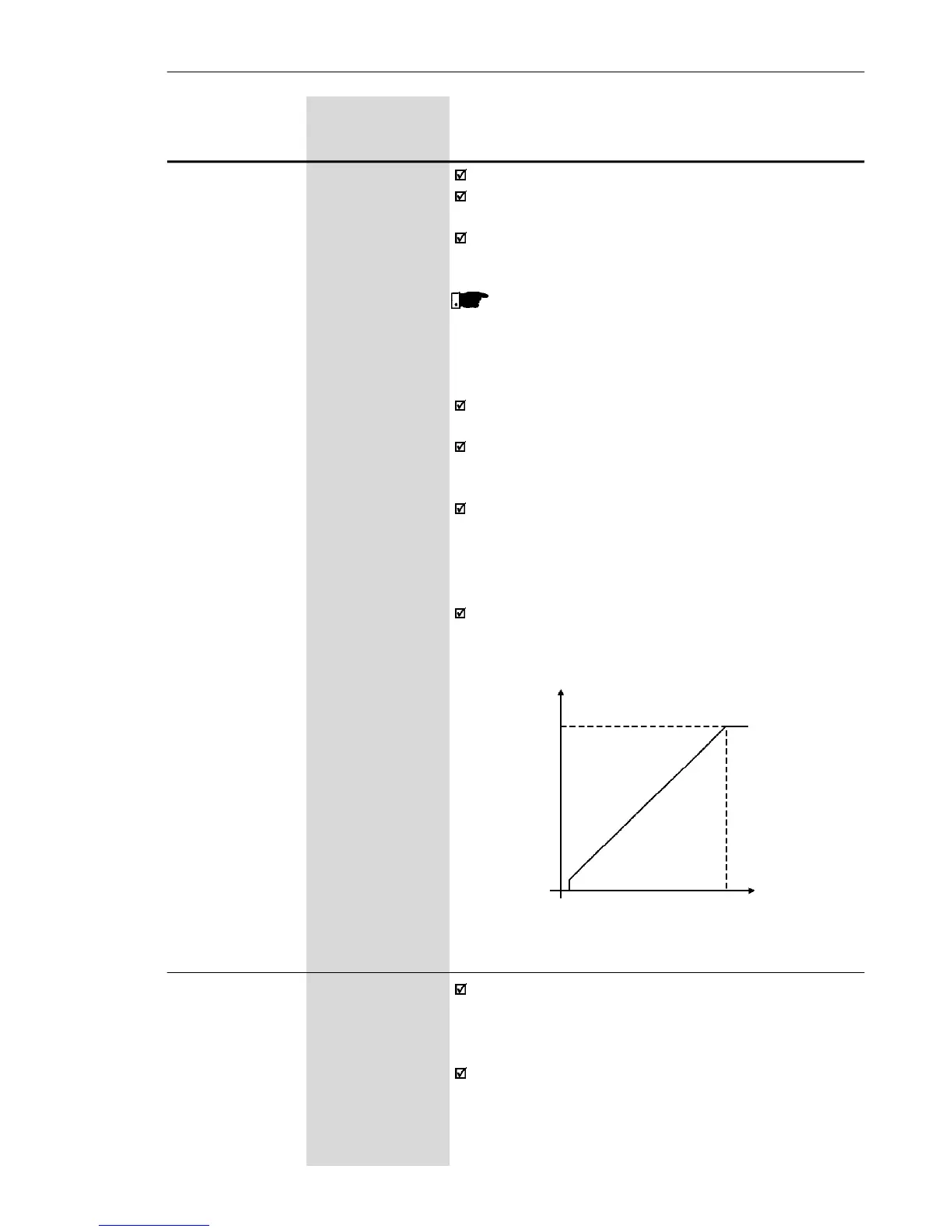
Figure 6.11 - Adjustable V/F curve
Ouput Voltage
Output
Frequency
P1450.1 Hz
0
P142
P151 360 to 460
DC Link Volage (line 110-127 V)
Regulation Level [ 430 ]
1 V
325 to 410
(line 200-240 V)
[ 380 ]
1 V
The DC link voltage regulation (ramp holding) avoids
inverter disable due to overvoltage trips (E01) during
deceleration of loads with high inertia or short
deceleration times.
It acts in order to increase the deceleration time
(according to load - inertia), thus avoiding the E01
activation.