70
CHAPTER 6 - DETAILED PARAMETER DESCRIPTION
Range
[Factory Setting]
Parameter Description / Notes
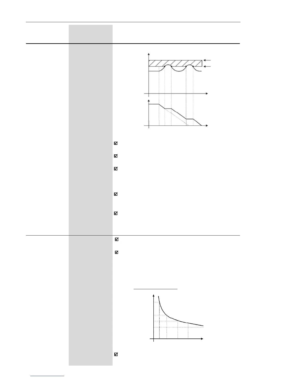
Figure 6.12 - Deceleration curve with DC Link voltage regulation
By this function an optimized deceleration time
(minimum) is achieved for the driven load.
This function is useful in applications with medium
inertia that require short deceleration times.
In case of overvoltage trip during the decelearation,
you must reduce gradually the value of P151 or
increase the time of the deceleration ramp (P101 and/
or P103).
The motor will not stop if the line is permanently with
overvoltage (U
d
> P151). In this case, reduce the line
voltage, or increase the value of P151.
If even with these settings the motor does not
decelerate within the required time, you will have the
alternative to increase P136;
E01 - Overvoltage
Hardware limit
CI Voltage
Ud (P004)
Time
Output
Frequency
(Motor
Speed )
Rated Ud
P151
Time
DC Link
Voltage
P156 0.3 x I
nom
to 1.3 x I
nom
Motor Overload [ 1.2 x P295 ]
Current 0.1 A
This function is used to protect the motor against
overload (I x t function - E05).
The motor overload current is the current level above
which the inverter will consider the motor operating
under overload. The higher the difference between the
motor current and the overload current, the sooner the
I x t function - E05 - will act.
Figure 6.13 - I x t function – Overload detection
Parameter P156 shall be set to a value 10 % to 20 %
higher than the motor rated current.
3.0
2.0
1.5
1.0
15 30 60 90
Time (s)
Motor Current (P003)
Overload Current