75
CHAPTER 6 - DETAILED PARAMETER DESCRIPTION
Range
[Factory Setting]
Parameter Description / Notes
P231
(1)
0 to 2
Forward/Reverse - [ 2 - Commands]
Local/Remote
Modes
Defines the direction of rotation.
P231
0
1
2
Direction of rotation
Always forward
Always reverse
Commands as defined in
P229 and P230
Table 6.9 - P231 programming to select rotation direction
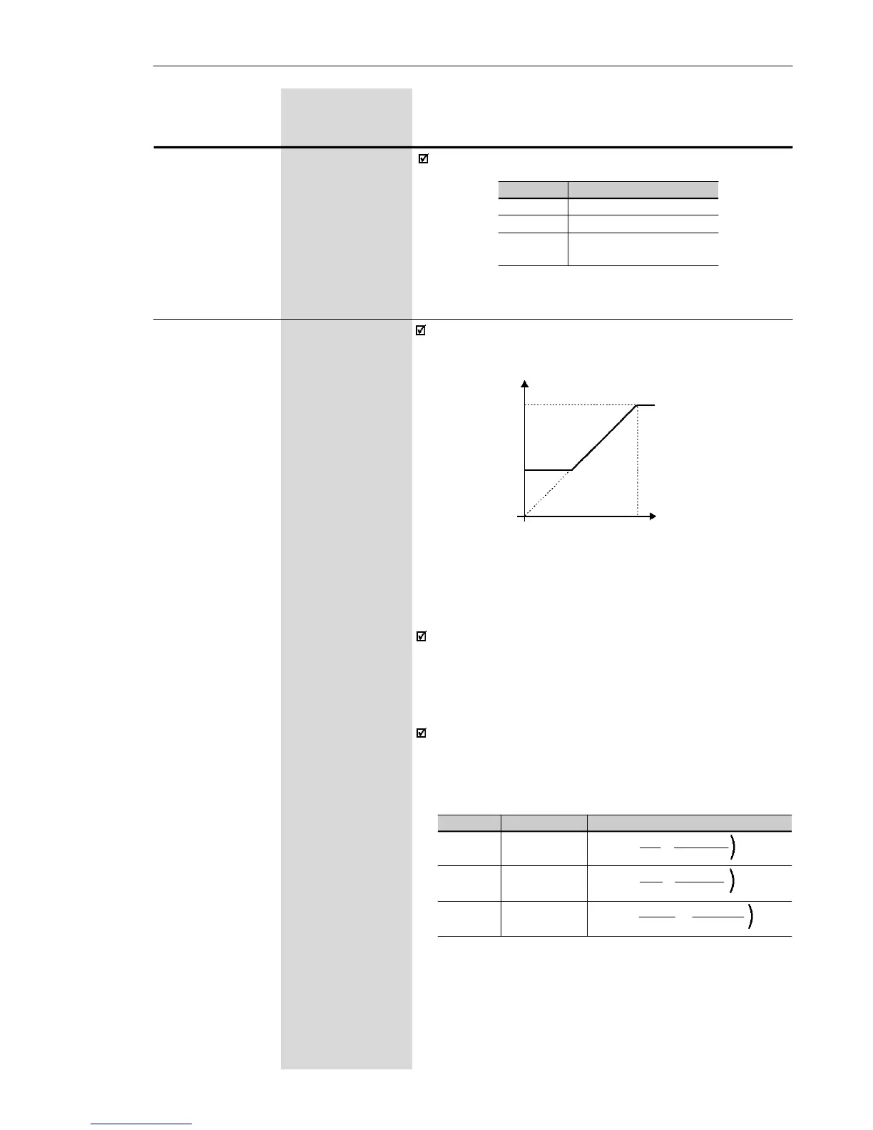
Note that there is always a dead zone at the starting of
the curve where the frequency reference remains at
the value of the minimum frequency (P133), even when
the input signal is changed. This dead zone is only
suppressed when P133 = 0.0.
The internal value AI1' that defines the frequency
reference to be used by the inverter, is given as percent
of the full scale reading and is obtained by using one
of the following equations (see P235):
Figure 6.17 a) - Analog Input AI1 Signal x Frequency reference
P234 0.0 to 999
Analog Input AI1 [ 100 ]
Gain 0.1 (< 100)
1 (> 99.9)
(Software
Version 2.0X)
The analog input AI1 defines the inverter frequency
reference as shown in the curve below.
P134
P133
AI
0
0 ...............100 %
0 ................. 10 V (P235 = 0)
0 .............. 20 mA (P235 = 0)
4 mA ......... 20 mA (P235 = 1)
Frequency Reference
P235
0
0
1
Signal
(0 to 10) V
(0 to 20) mA
(4 to 20) mA
Equation
AI1' =
AI1
+
OFFSET
. GAIN
10 100
AI1' =
AI1
+
OFFSET
. GAIN
20 100
AI1' =
AI1-4
+
OFFSET
. GAIN
16 100
(
(
(
Table 6.10 a) - Analog input signal AI1 (P235) definition
Where:
- AI1 is given in V or mA, according to the used signal
(see parameter P235);
- GAIN is defined by the parameter P234;
- OFFSET is defined by the parameter P236.