76
CHAPTER 6 - DETAILED PARAMETER DESCRIPTION
Range
[Factory Setting]
Parameter Description / Notes
This is shown in the block diagram below:
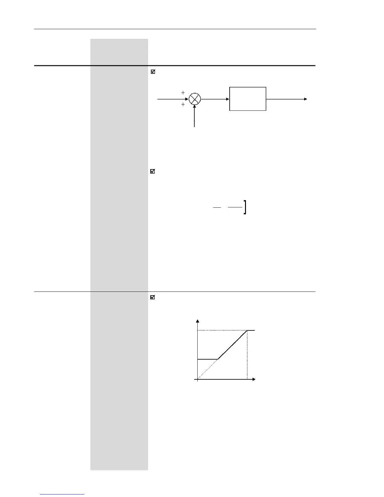
GAIN
P234
AI1'
OFFSET
(P236)
P235
AI1
Figure 6.18 a) - Block diagram of the analog input A1
Following situation as example: AI1 is thevoltage input
(0-10 V - P235 = 0), AI1 = 5 V, P234 = 1.00 and
P236 = -70 %. Thus:
The motor will run in reverse direction of rotation as
defined by the commands (negative value) - if this is
possible (P231 = 2), with a module reference equal to
0.2 or 20 % of the maximum output frequency (P134).
I.e., if P134 = 66.0 Hz, then the frequency reference is
equal to 13.2 Hz.
AI1'
=
5
+
(-70)
.
1
=
-0.2
=
-20 %
10 100
[
P234 0.0 to 999
Analog Input AI1 [ 100 ]
Gain 0.1 (< 100)
1 (> 99.9)
(Software
Version 2.2X)
The analog input AI1 defines the inverter frequency
reference as shown in the curve below.
Figure 6.17 b) - Analog Input AI1 Signal x Frequency reference
P134
P133
AI
0
0 ...............100 %
0 ................. 10 V (P235 = 0)
0 .............. 20 mA (P235 = 0)
4 mA ......... 20 mA (P235 = 1)
Frequency Reference