77
CHAPTER 6 - DETAILED PARAMETER DESCRIPTION
Range
[Factory Setting]
Parameter Description / Notes
Note that there is always a dead zone at the starting of
the curve where the frequency reference remains at
the value of the minimum frequency (P133), even when
the input signal is changed. This dead zone is only
suppressed when P133 = 0.0.
The internal value AI1' that defines the frequency
reference to be used by the inverter, is given as percent
of the full scale reading and is obtained by using one
of the following equations (see P235):
Where:
- AI1 is given in V or mA, according to the used signal
(see parameter P235);
- GAIN is defined by the parameter P234;
- OFFSET is defined by the parameter P236.
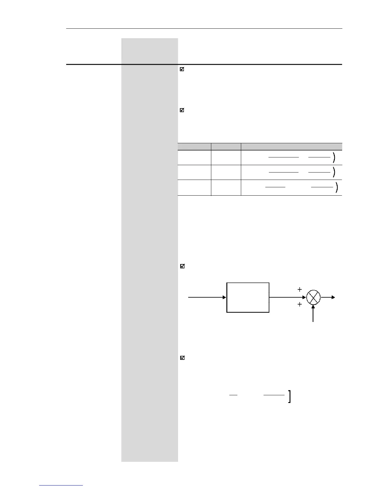
This is shown in the block diagram below:
Figure 6.18 b) - Block diagram of the analog input A1
Table 6.10 b) - Analog input signal AI1 (P235) definition
P235
0
0
1
Signal
0 to 10 V
0 to 20 mA
4 to 20 mA
Equation
AI1' =
AIx . GAIN
+
OFFSET
10 100
AI1' =
AIx . GAIN
+
OFFSET
20 100
AI1' =
(AIx - 4)
. GAIN
+
OFFSET
16 100
(
(
(
GAIN
P234
AI1'
P235
AI1
OFFSET (P236)
Following situation as example: AI1 is the voltage
input (0-10 V - P235 = 0), AI1 = 5 V, P234 = 1.00
and P236 = -70 %.
Thus:
The motor will run in reverse direction of rotation as
defined by the commands (negative value) - if this is
possible (P231 = 2), with a module reference equal to
0.2 or 20 % of the maximum output frequency (P134).
I.e., if P134 = 66.0 Hz, then the frequency reference is
equal to 13.2 Hz.
AI1'
=
5
.
1.00 +
(-70)
=
-20 %
10 100
[