78
CHAPTER 6 - DETAILED PARAMETER DESCRIPTION
Range
[Factory Setting]
Parameter Description / Notes
P235
(1)
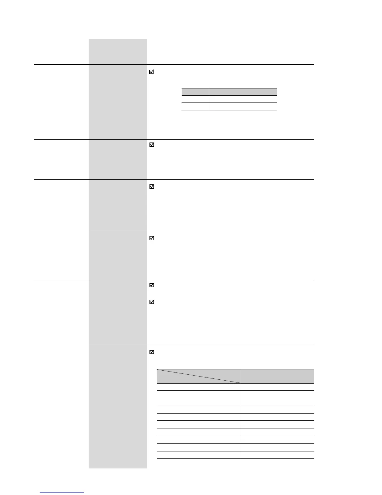
0 to 1
Analog Input AI1 [ 0 ]
Signal
Defines the signal type of the analog input, as shown
in table below:
P236 -120 to +120
Analog Input AI1 [ 0 ]
Offset 1 %
See P234.
P235
0
1
Signal Type
(0 to10) V or (0 to 20) mA
(4 to 20) mA
P248 0 to 200
Analog Inputs [ 200 ]
Filter Time 1 ms
Constant
It configures the time constant of the analog inputs filter
between 0 (without filtering) and 200 ms.
Thus the analog input will have a response time equal
to three time constants. For instance, if the time
constant is 200 ms, and a step is applied to the analog
input, the response will be stabilized after 600 ms.
P263
(1)
0 to 27
Digital Input DI1 [ 1 - Not used (HMI)
Function or General Enable
(Terminals) ]
-
P264
(1)
0 to 27
Digital Input DI2 [ 5 - FWD/REV ]
Function -
P265
(1)
0 to 27
Digital Input DI3 [ 6 - Local/Remote ]
Function -
Check possible options on table below and details
about each function operation in Figure 6.19.
Table 6.11 - P235 setting according to signal type/excursion
P238 0.0 to 999
Input Gain [ 100 ]
(HMI 0.1(< 100)
Potentiometer) 1(> 99.9)
See P234.
P240 -120 to +120
Input Offset [ 0 ]
(HMI 1 %
Potentiometer)
See P234.
DI Parameter DI1 (P263), DI2 (P264),
Function DI3 (P265), DI4 (P266)
Not used 0
Not used (HMI) or 1
General Enable (Terminals)
General Enable 2
JOG 3
Start/Stop 4
FWD/REV 5
Local/Remote 6
Multispeed 7
Multispeed with Ramp 2 8
Table 6.12 - DI´s functions programming