93
CHAPTER 6 - DETAILED PARAMETER DESCRIPTION
2) Automatic Operation: open the DI and make the dynamic setting of
the PID regulator, i.e., set the proportional gain (P520), integral
gain (P521) and differential gain (P522).
NOTE!
The inverter setting must be correct in order to obtain a good
performance of the PID regulator. Ensure the following settings:
Torque boosts (P136 and P137) and slip compensation (P138) in
the V/F mode control (P202 = 0 or 1);
Acceleration and deceleration ramps (P100 to P103);
Current limitation (P169).
Inverter parameterization:
P203 = 1 P238 = 100
P221 = 0 or 3 P240 = 0
P222 = 0 or 3 P265 = 27
P229 = 1 P525 = 0
P234 = 100 P526 = 0.1
P235 = 1 P527 = 0
P236 = 000 P528 = 25
CFW-10
P525
Content
The set point can be
changed through keys or
potentiometer according to
P221/P222
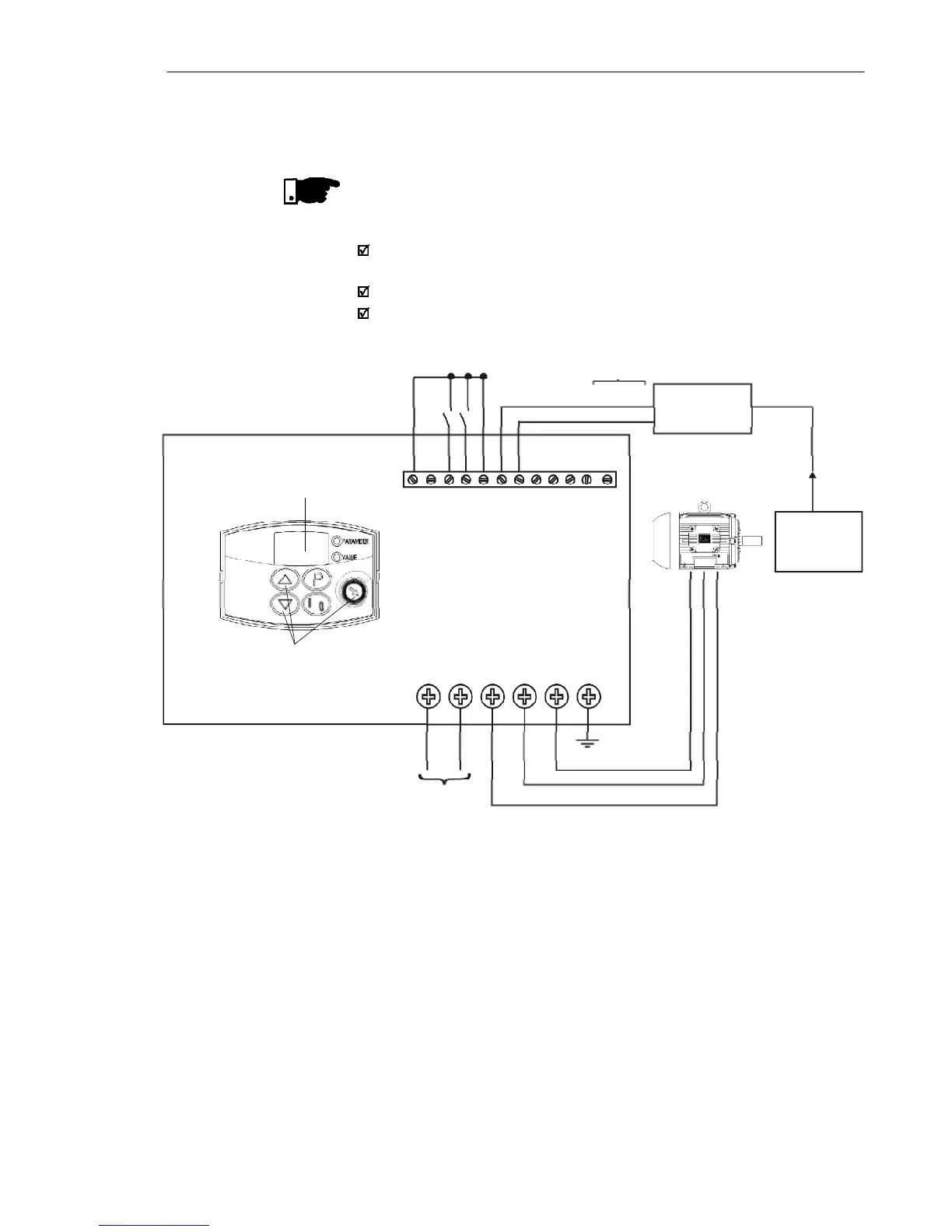
X1
L/L1 N/I2 U V W PE
Line
1 2 3 4 5 6 7 8 9 10111 2
DI1 Gen. enable
DI3-Manual/Auto
DI4-Run/Stop
AI1 - Feedback
Pressure
Transducer
4-20 mA
0-25 bar
Process
Figure 6.24 - Application example of an inverter with PID regulator
Input via terminals 6 and 7