10
CFW-08 -
QUICK PARAMETER REFERENCE
Only available
in CFW-08
Plus version.
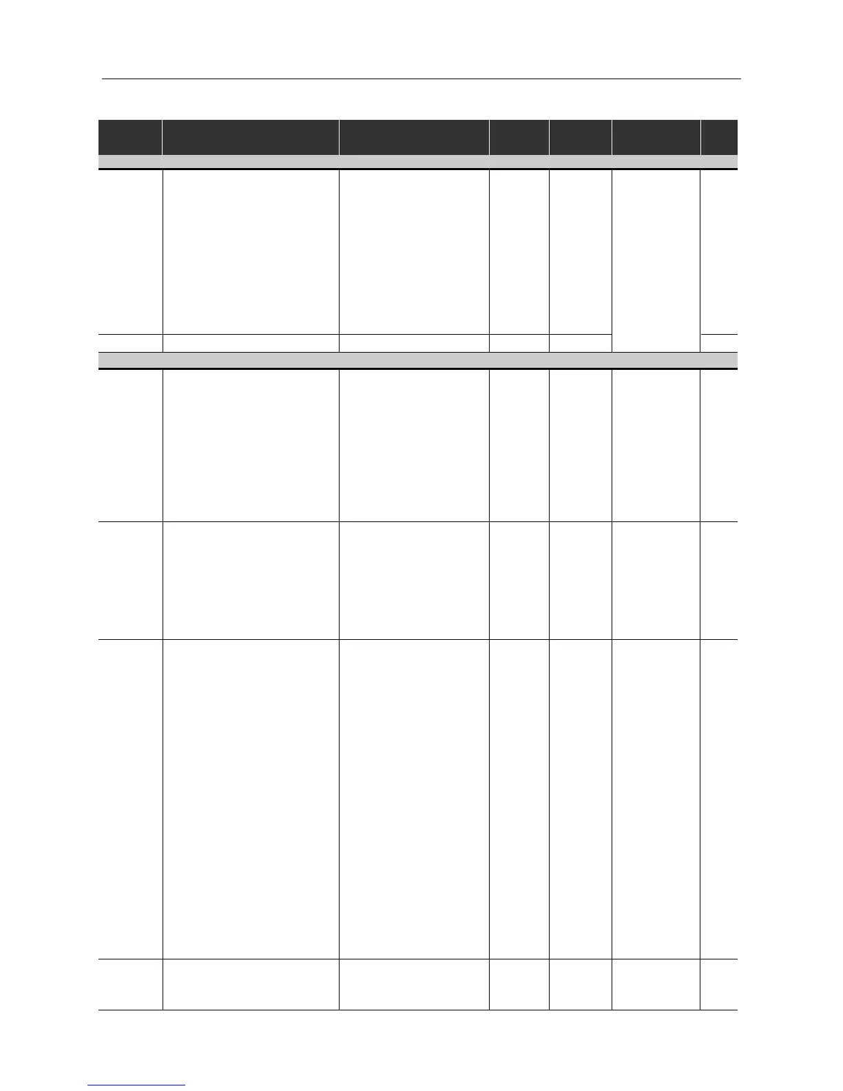
Analog Output
0 = Output Frequency (Fs)
1 = Input Reference (Fe)
2 = Output Current (Is)
3, 5, 8 = Not used 88
P251 Analog Output 4 = Motor Torque 0
AO Function 6 = Process Variable
(PID)
7 = Active Current
9 = PID Setpoint
P252 Analog Output AO Gain 0.00 ... 9.99 1.00 88
Digital Inputs
P263
(1)
Digital Input DI1 Function
0 = No Function or
089
General Enable
1 ... 7 and 10 ... 12 =
General Enable
8 = Forward Run
9 = Start/Stop
13 = FWD Run Using
Ramp #2
14 = Start (3-wire)
P264
(1)
Digital Input DI2 Function
0 = Forward/Reverse
089
1 = Local/Remote
2 ... 6 and 9 ... 12 = Not used
7 = Multispeed (MS2)
8 = Reverse
13 = REV Run - Ramp #2
14 = Stop (3-wire)
P265
(1) (2)
Digital Input DI3 Function
0 = Forward/Reverse
10 89
1 = Local/Remote
2 = General Enable
3 = JOG
4 = No External Fault
5 = Increase E.P.
6 = Ramp #2
7 = Multispeed (MS1)
8 = No Function or
Start/Stop
9 = Start/Stop
10 = Reset
11, 12 = Not used
13 = Flying Start Disable
14 = Multispeed (MS1)
Using Ramp #2
15 = Manual/Automatic PID)
16 = Increase E.P. with
Ramp #2
P266
(1)
Digital Input DI4 Function
0 = Forward/Reverse
889
1 = Local/Remote
2 = General Enable
(1)
This parameter can be changed only with the inverter disabled (motor stopped).
(2)
Value may change as a function of P203.
Parameter Function
Adjustable Range
Factory User
Note Page
Setting Setting