45
INSTALLATION AND CONNECTION
Obs.:
1) Category II systems must be mounted inside a metallic cabinet in
order to have radiated emissions below the limits for first environment
and restricted distribution (see item 3.3.3). Category I systems do not
require a metallic cabinet. Exception: models 7 and 8, that need to be
mounted inside a cabinet to pass in the radiated emission test for
second environment and unrestricted distribution (see item 3.3.3). When
a metallic cabinet is required, the maximum length of the remote keypad
cable is 3m. In this case, the control (I/O) and signal wiring must be
located inside the cabinet and the remote keypad can be installed in
the cabinet front door (see items 8.3.1 and 8.5).
2) The maximum switching frequency is 10kHz. Exception: 5kHz for
models 24 up to 33 (category I, 380-480V models). For category I
systems see also note 7.
3) The maximum motor cable length is 20m for models 9, 10, 11, 12, 13,
14, 15, 16, 17, 18, 19, 20, 21, 22, 23, 34, 35, 36 and 37, 10m for
models 1, 2, 3, 4, 5, 6, 7, 8, 24, 25, 26, 27, 38, 39, 40, 41, 42 and 43
and 5m for models 28, 29, 30, 31, 32 and 33. For category I systems
see also note 7.
4) In models 28, 29, 30 and 31 (see also note 7), a CM choke at inverter
output is required: TOR1-CFW08, 1 turn. The toroid is mounted inside
the N1 kit that is provided with these models. For installation see figure
3.15.
5) In models 38, 39, 40, 41, 42 and 43, a CM choke at filter input is
required: TOR2-CFW08, 3 turns. For installation see figure 3.15.
6) In models 38, 39, 40 and 41, it is required to use a shielded cable
between the external filter and the inverter.
7) Category I systems were also tested using second environment
unrestricted distribution limits for conducted emissions (for definitions
see notes 2 and 3 of item 3.3.3). In this case:
- the maximum cable length is 30m for models 1, 2, 3, 4, 5, 6, 7, 8,
32 and 33 and 20m for models 24, 25, 26, 27, 28, 29, 30 and 31;
- the maximum switching frequency is 10kHz for models 28, 29, 30
and 31 and 5kHz for models 1, 2, 3, 4, 5, 6, 7, 8, 24, 25, 26, 27, 32
and 33;
- models 28, 29, 30 and 31 do not require any CM choke at inverter
output (as stated in note 4).
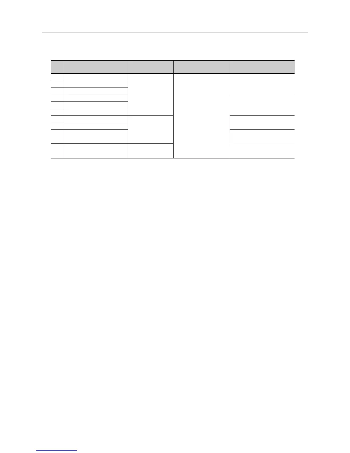
Id Inverter Model
34 CFW080010T3848...
35 CFW080016T3848...
36 CFW080026T3848...
37 CFW080040T3848...
38 CFW080027T3848...
39 CFW080043T3848...
40 CFW080065T3848...
41 CFW080100T3848...
42 CFW080130T3848...
43 CFW080160T3848...
Input RFI Filter
FN3258-7-45
(external filter)
FN3258-16-45
(external filter)
FN3258-30-47
(external filter)
EMC Category
Category II (domestic)
Dimensions
(Width x Height x Depth)
Inverter: 75x151x131mm
Filter: 40x190x70mm
Inverter: 115x200x150mm
Filter: 40x190x70mm
Inverter: 115x200x150mm
Filter: 45x250x70mm
Inverter: 143x203x165mm
Filter: 45x250x70mm
Inverter: 143x203x165mm
Filter: 50x270x85mm
Table 3.6 - Inverter models list with filters and EMC category