68
DETAILED PARAMETER DESCRIPTION
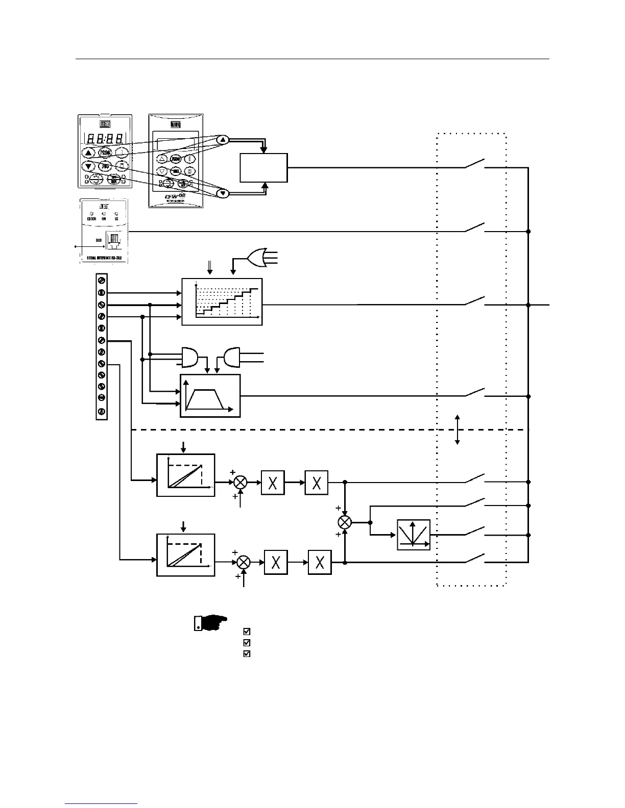
Figure 6.1 - Block diagram of the frequency reference
NOTE!
AI2 is only available in CFW-08 Plus version.
DIs ON when connected to 0V (XC1:5).
When F*<0 one takes the module of F* and reverses the direction of
rotation (if this is possible - P231=2 and if the selected control is not
forward run/reverse run.
RS-232
PC, CLP,
MIW-02
KEYPAD
REFERENCE
(P121)
HMI-CFW08-RP
or
HMI - CFW08-RS
KCS-CFW-08
P124...P131
P264=7
P265=7
P266=7
MULTISPEED
Accel.
Enabling Function
P265=5
P266=5
Decel.
Inverter
Disabled
ELECTRONIC POTENTIOMETER (EP)
AI2
AI1
DI4
DI3
DI2
1
2
3
4
5
6
7
8
9
10
11
12
XC1
AI1
P235
AI2
P239
P238 P134
P234
P134
P236
P240
2 or 3 - AI2
7 - Add AI>0
8 - Add AI1
1 - AI
4 - EP
6 - Multispeed
5 - Serial
0 - Keypad
Frequency Reference
Selection
P221 or P222
F*
Digital
References
Analog
References
P131
P130
P129
P128
P127
P126
P125
P124
000 001 010 011 100 101 110 111
100%
P239=0
P239=1
0
2V/4mA
10V/20mA
100%
P235=0
P235=1
0
2V/4mA 10V/20mA
0V
Reset
HMI-CFW08-P