80
DETAILED PARAMETER DESCRIPTION
Range
[Factory Setting]
Parameter Unit Description / Notes
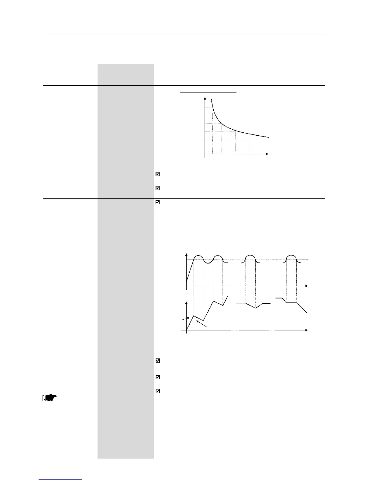
Figure 6.13 - Ixt function – Overload detection
3,0
2,0
1,5
1,0
15 30 60 90
Time (s)
Motor Current (P003)
Overload Current
Prevents motor stalling during an overload. If motor load increases
its current will increase too. If the motor current attempts to exceed
the value set at P169, the motor speed will be decreased by following
the deceleration ramp until the current becomes lower than P169.
As soon as the overload condition disappears, the motor speed is
resumed.
P169 0.2xPI
nom
...2.0xPI
nom
Maximum Output [ 1.5xP295 ]
Current 0.01A (<10.0A);
0.1A (>9.99A)
Parameter P156 must be set from 10% to 20% higher than the
rated motor current (P401).
Always P401 is changed, P156 is adjusted automatically to
1.1xP401.
Figure 6.14 – Curves showing the actuation of the current limitation
Time
during
cont. duty
Time
Motor Current
Deceleration ramp (P101/P103)
decel.
ramp
accel.
ramp
during
deceleration
during
acceleration
acceleration
ramp
(P100/P102)
Speed
P169
The current limitation function is disabled when P169>1.5xP295.
P178 50.0...150.0%
Rated Flux [ 100% ]
0.1% (<100%);
1% (>99.9%)
This
parameter is shown
only in vector
control (P202=2)
Defines the flux in the motor air gap, when in vector control. It is
expressed as a percentage (%) of the nominal flux.
Generally it is not necessary to change P178 of the default value
(100%). But in some specific cases, different values at P178 may
be set.These conditions may be:
- to increase the inverter torque capacity (P178>100%).
Examples:
1) to increase the motor starting torque and thus ensure faster
motor starts;
2) to increase the inverter braking torque and thus allow faster
stops, without using dynamic braking.
- to reduce the inverter energy consumption (P178<100%).