79
DETAILED PARAMETER DESCRIPTION
Range
[Factory Setting]
Parameter Unit Description / Notes
P151 325...410V
DC Link Voltage (line 200-240V)
Regulation Level [ 380V ]
1V
564...820V
(line 380-480V)
[ 780V ]
1V
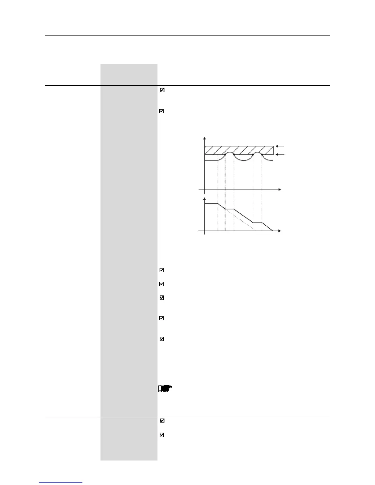
The DC link voltage regulation (ramp holding) avoids overvoltage
trips (E01) during deceleration of high inertia loads and/or short
deceleration times.
It acts in order to increase the deceleration time (according to load
- inertia), thus avoiding the E01 activation.
E01 - Overvoltage
CI limitation
Cl voltage
Ud (P004)
Time
Output
Frequnecy
(Motor
speed)
rated Ud
P151
Time
Figure 6.12 - Deceleration curve with DC Link voltage limitation
(regulation)
By this function an optimized deceleration time (minimum) is
achieved for the driven load.
This function is useful in applications with medium inertia that require
short deceleration times.
In case of overvoltage trip during the decelearation, you must reduce
gradually the value of P151 or increase the time of the deceleration
ramp (P101 and/or P103).
The motor will not stop if the line is permanently with
overvoltage (U
d
>P151). In this case, reduce the line voltage,
or increase the value of P151.
If even with these settings the motor does not decelerate within the
required time, you will have the following alternatives
- use the dynamic braking (for more details, see Item 8.20);
- if inverter is being operated in V/F control, increase P136;
- if inverter is being operated in vector control, increase P178.
NOTE!
When dynamic braking is used, set P151 to the maximum
value.
P156 0.2xPI
nom
...1.3xPI
nom
Motor Overload [ 1.2xP401 ]
Current 0.01A (<10.0A);
0.1A (>9.99A)
This function is used to protect the motor against overload
(Ixt function - E05).
The motor overload current is the current level above which the in
verter will consider the motor operating under overload. The higher
the difference between the motor current and the overload current,
the sooner the Ixt function - E05 - will act.
DC Link
voltage