78
DETAILED PARAMETER DESCRIPTION
Range
[factory Setting]
Parameter Unit Description / Notes
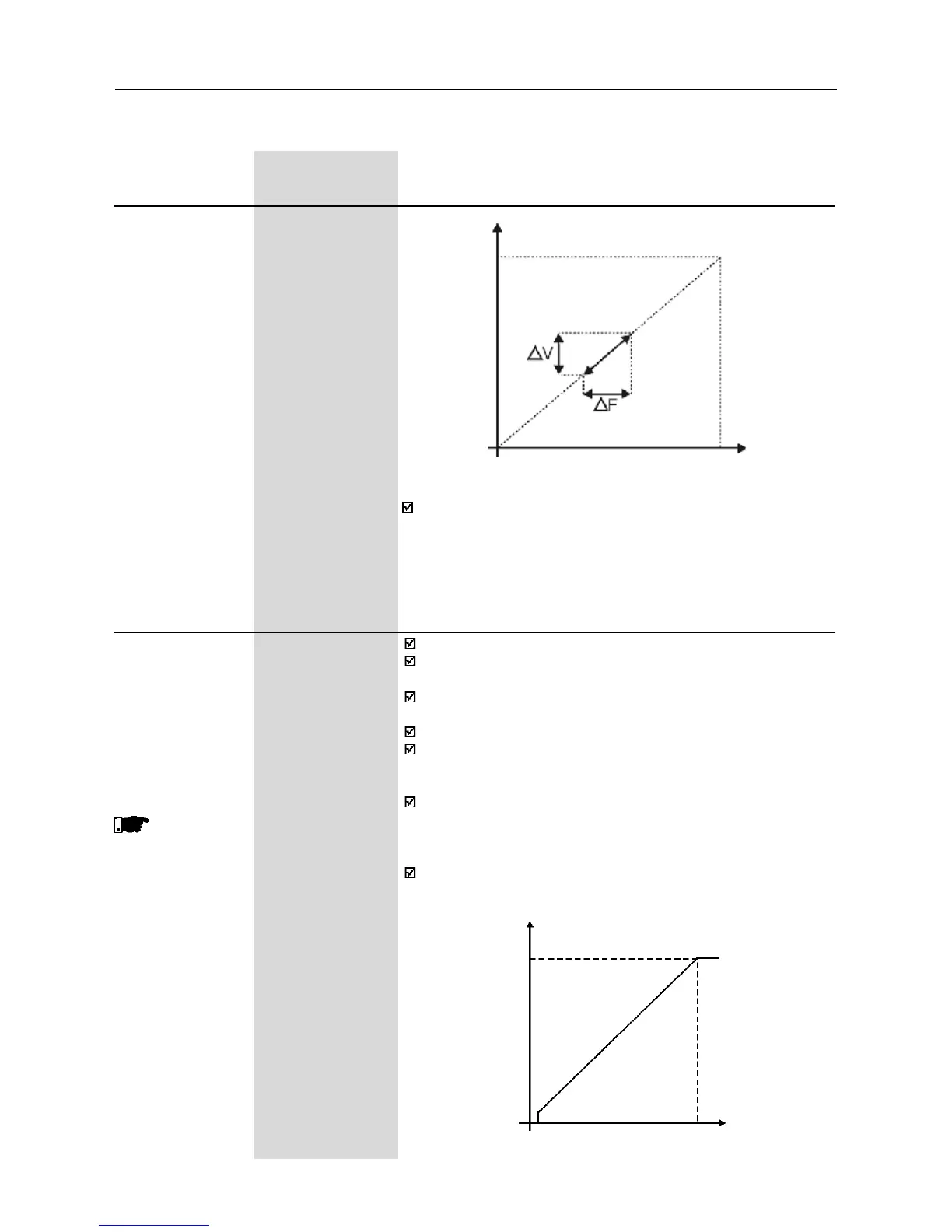
Figure 6.10 - V/F curve with slip compensation
Output Voltage
(function of
the motor
load)
Output
Frequency
To set the parameter P138 use the following procedure:
- run the motor without load up to approximately half of the application
top speed;
- measure the actual motor or equipment speed;
- apply rated load to equipment;
- increase parameter P138 until the speed reaches its no-load speed.
P142
(1)
0...100%
Maximum Output
Voltage [ 100% ]
1%
P145
(1)
P133...P134
Field Weakening [ 60.00Hz ]
Frequency 0.01Hz (<100.0)
(F
nom
) 0.1Hz (>99.99)
These
parameters are
only available in
V/F control
(P202=0 or 1)
Define the V/F curve used in V/Fcontrol (P202=0 or 1).
These parameters allow changing the standard V/F curve defined
at P202 - programmable V/F curve.
P142 sets the maximum output voltage. This value is set
as a percent of the inverter supply voltage.
Parameter P145 defines the rated frequency of the motor used.
The V/F curve relates the inverter output voltage and frequency
(applied to the motor) and consequently the magnetizing flux of the
motor.
The programmave V/F curve can be used in special applications
where the motors used require a rated voltage and/or frequency
different than the standard ones. Examples: motor for 220V/
400Hz and a motor for 200V/60Hz.
Parameter P142 is also useful in appplications that require
rated voltage different from the inverter supply voltage. Example:
440V line and 380V motor.
Figure 6.11 - Adjustable V/F curve
Output Voltage
Output
Frequency
P1450.1Hz
0
P142
(1)
This parameter can be changed only with the inverter disabled (motor stopped).