77
DETAILED PARAMETER DESCRIPTION
Range
[Factory Setting]
Parameter Unit Description / Notes
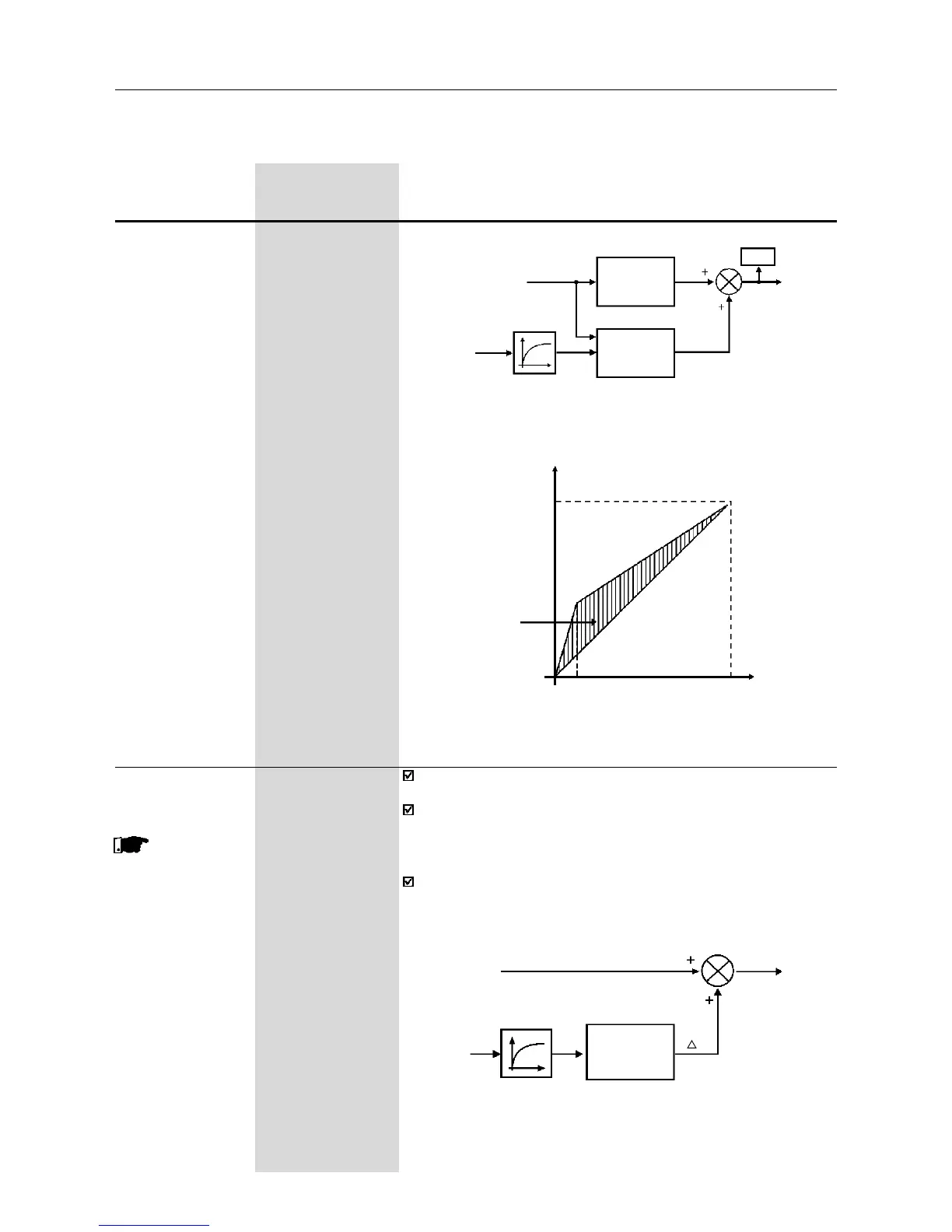
Figure 6.7 - Block diagram of the automatic torque boost function
Compensation
Zone
Maximum
(P142)
Output Voltage
Output
Frequency
Field Weakening
(P145)
4H z
0
Figure 6.8 - V/F curve with automatic torque boost
(automatic IxR compensation )
Speed
Reference (F*)
Output Active
Current (I
a
)
Filer
Automatic
Torque Boost
P137
Manual
Torque Boost
P136
P007
Motor
Voltage
P138 0.0...10.0%
Slip Compensation [0.0]
0.1%
This parame-
ter is only available
in V/F control
(P202=0 or 1)
The parameter P138 is used in the motor slip compensation function.
This function compensates the drop of the motor speed due to
load, which is a inherent characteristic relating to the operation
principle of the induction motor.
This speed drop is compensated by increasing the output frequency
(and voltage) (applied to the motor) as a function of the increase of
the active motor current, as shown in the block diagram and in the
V/F curve below.
Slip
Compensation
Output Active
Current (I
a
)
Frequency
Reference (F*)
Ramp Input
Frequency (Fe)
F
Filter
P138
Figure 6.9 - Block diagram of the slip compensation function