76
DETAILED PARAMETER DESCRIPTION
Range
[Factory Setting]
Parameter Unit Description / Notes
P133
(1)
0.00...P134
Minimum Frequency [ 3.00Hz ]
(F
min
) 0.01Hz (<100.0);
0.1Hz (>99.99)
P134
(1)
P133...300.0
Maximum Frequency [ 66.00Hz ]
(F
max
) 0.01Hz (<100.0);
0.1Hz (>99.99)
Defines the maximum and minimum output frequency (motor)
when inverter is enabled.
It is valid for any type of speed reference.
The parameter P133 defines a dead zone when analog inputs are
used - see parameters P234 ... P240.
P134 and the gain and offset of the analog input(s) (P234, P236,
P238 and P240) define the scale and the range of the speed
variation via analog input(s). For more details see parameters
P234 ... P240.
P136 0.0...30.0%
Manual Torque [ 5.0% for
Boost 01.6-2.6-4.0-7.0A/
(IxR Compensation) 200-240V and
1.0-1.6-2.6-4.0A/
380-480V;
2.0% for
7.3-10-16A/
200-240V and
2.7-4.3-6.5-10A/
380-480V;
1.0% for
13-16A/380-480V ]
0.1%
Compensates the voltage drop due to the motor stator resistance.
It acts at low speeds by increasing the inverter output voltage,
in order to maintain a constant torque during the V/F operation.
The best setting is to program the lowest value for P136 that still
permits the motor start satisfactorily. If the value is higher than
required, an inverter overcurrent (E00 or E05) may occur due to
high motor currents at low speeds.
This parame-
ter is only available
in V/F control
(P202=0 or 1)
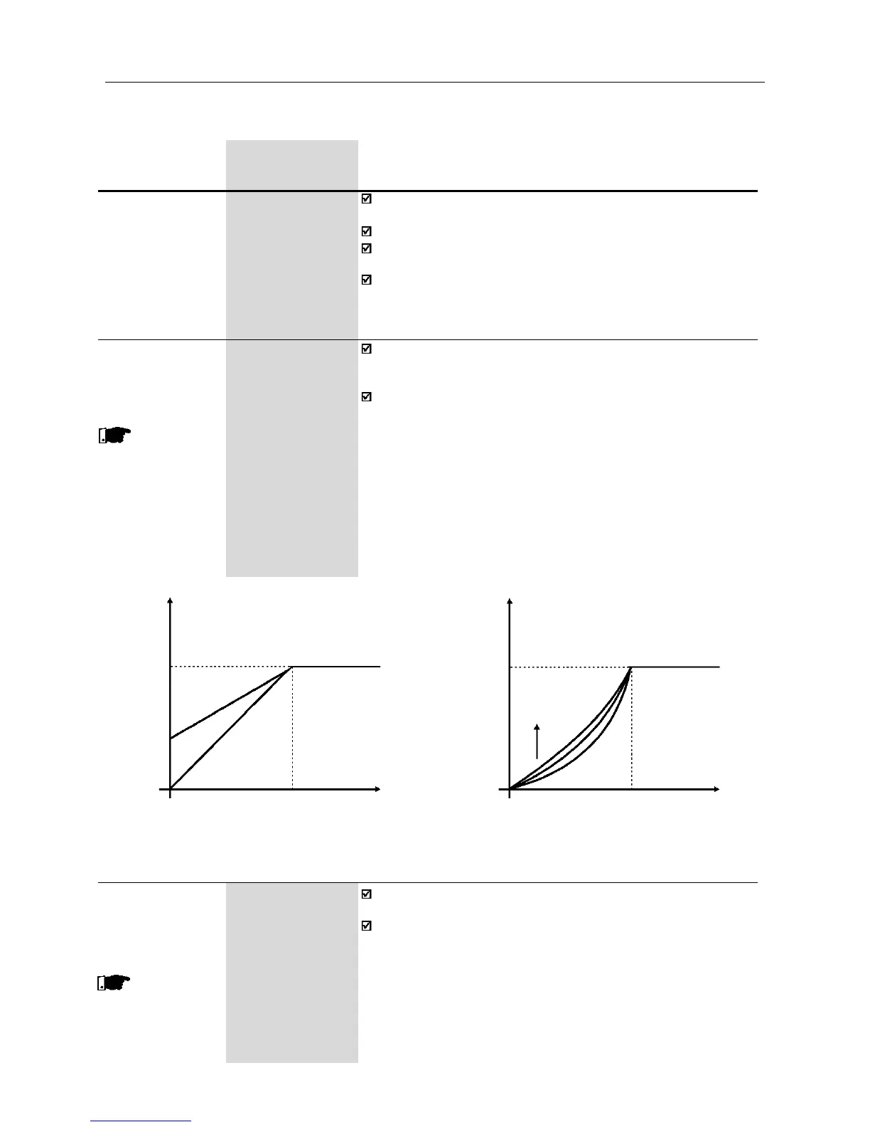
Figure 6.6 - V/F curve and details of the manual torque boost (IxR compensation)
Output Voltage
(% of the line voltage)
Output Voltage
(% of the line voltage)
P142
P136xP142
0 P145
Output
Frequency
P142
P136
0 P145
Output
Frequency
(a) P202=0 (b) P202=1
P137 0.00...1.00%
Automatic Torque [ 0.00 ]
Boost -
(Automatic IxR
Compensation)
This parame-
ter is shown only in
V/F control
(P202=0 or 1)
The automatic torque boost compensates for the voltage drop in
the stator resistance as a function of the active motor current.
The criteria for setting P137 are the same as for the parameter
P136.
(1)
This parameter can be changed only with the inverter disabled (motor stopped).