75
DETAILED PARAMETER DESCRIPTION
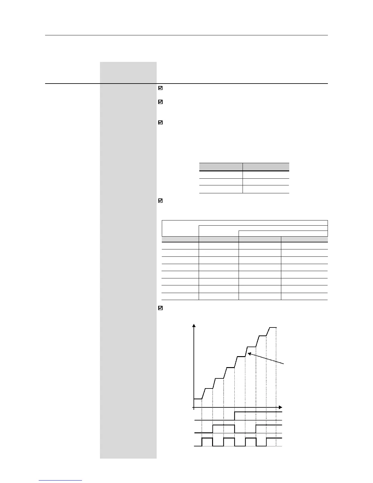
Multispeed is used when the selection of a number up to 8 pre-
programmed speeds is desired.
It allows the control of the output speed by relating the values
programmed by the parameters P124...P131, according to the
logical combination of the digital inputs programmed for multispeed.
Activation of the multispeed function:
- ensure that the reference source is given by the multispeed
function, i.e., set P221=6 in local mode or P222=6 in remote
mode;
- program one or more digital inputs to para multispeed, according
to table below:
DI Programming
DI2 P264 = 7
DI3 P265 = 7
DI4 P266 = 7
The frequency reference is defined by the status of the digital inputs
programmed to multispeed as shown in table below:
The multispeed function has some advantages for the stabibilty of
the fixed preprogrammed references and the immunity against
electrical noises (digital references and insulated digital inputs).
(1)
This parameter can be changed only with the inverter disabled (motor stopped).
Range
[Factory Setting]
Parameter Unit Description/Notes
P124
(1)
P133...P134
Multispeed Ref. 1 [ 3.00Hz ]
0.01Hz (<100.0);
0.1Hz (>99.99)
P125
(1)
P133...P134
Multispeed Ref. 2 [ 10.00Hz ]
0.01Hz (<100.0);
0.1Hz (>99.99)
P126
(1)
P133...P134
Multispeed Ref. 3 [ 20.00Hz ]
0.01Hz (<100.0);
0.1Hz (>99.99)
P127
(1)
P133...P134
Multispeed Ref. 4 [ 30.00Hz ]
0.01Hz (<100.0);
0.1Hz (>99.99)
P128
(1)
P133...P134
Multispeed Ref. 5 [ 40.00Hz ]
0.01Hz (<100.0);
0.1Hz (>99.99)
P129
(1)
P133...P134
Multispeed Ref. 6 [ 50.00Hz ]
0.01Hz (<100.0);
0.1Hz (>99.99)
P130
(1)
P133...P134
Multispeed Ref. 7 [ 60.00Hz ]
0.01Hz (<100.0);
0.1Hz (>99.99)
P131
(1)
P133...P134
Multispeed Ref. 8 [ 66.00Hz ]
0.01Hz (<100.0);
0.1Hz (>99.99)
DI2 DI3 DI4 Freq. Reference
Open Open Open P124
Open Open 0V P125
Open 0V Open P126
Open 0V 0V P127
0V Open Open P128
0V Open 0V P129
0V 0V Open P130
0V 0V 0V P131
8 speeds
4 speeds
2 speeds
Figure 6.5 - Time diagram of the multispeed function
Acceleration
ramp
Time
0V
DI2
DI3
DI4
open
0V
open
0V
open
P124
P125
P126
P127
P128
P129
P130
P131
Output
frequency