89
DETAILED PARAMETER DESCRIPTION
P263
(1)
0...14
Digital Input DI1 [ 0 - Not used
Function or General Enabling]
-
P264
(1)
0...14
Digital Input DI2 [ 0 - FWD/REV ]
Function -
P265
(1)
0...15
Digital Input DI3 [ 10 - Reset ]
Function -
P266
(1)
0...15
Digital Input DI4 [ 8 - Not used
Function [Start/Stop ]
-
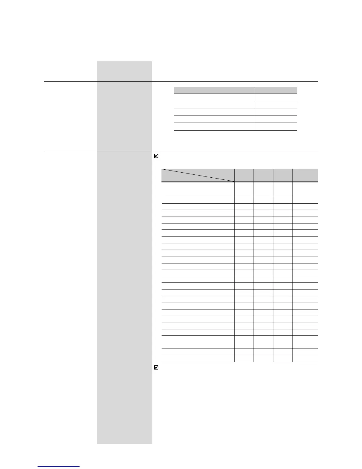
Check possible options on table below and details about each
function operation on Figure 6.19.
DI Parameter DI1 DI2 DI3 DI4
Function (P263) (P264) (P265) (P266)
General Enable
1...7 and
-2 2
10...12
Start/Stop 9 - 9 9
No Function or Start/Stop 0 - - -
No Function or Start/Stop - - 8 8
Forward Run 8 - - -
Reverse Run - 8 - -
FWD with Ramp #2 13 - - -
REV with Ramp #2 - 13 - -
Start (3-wire) 14 - - -
Stop (3-wire) - 14 - -
Multispeed - 7 7 7
Multispeed with ramp #2 - - 14 -
Increase EP - - 5 -
Decrease EP - - - 5
FWD/REV - 0 0 0
Local/Remote - 1 1 1
JOG - - 3 3
No external fault - - 4 4
Ramp #2 - - 6 6
Reset - - 10 10
Disable Flying Start - - 13 13
Manual/Automatic (PID) - - 15 -
Not used
- 2...6 and 11 and 11, 12,
9...12 12 14 and 15
Increase EP with Ramp #2 - - 16 -
Decrease EP with Ramp #2 - - - 16
(1)
This parameter can be changed only with the inverter disabled (motor stopped).
Range
[Factory Setting]
Parameter Unit Description / Notes
Functions activated with 0V at digital input.
Variable
Frequency (P251=0 or 1)
Current (P251=2 or 7)
Torque (P251=4)
Process variable - PID (P251=6)
Setpoint PID (P251=9)
Full scale
P134
1.5xI
nom
150%
P528
P528