95
DETAILED PARAMETER DESCRIPTION
(1)
This parameter can be changed only with the inverter disabled (motor stopped).
Range
[Factory Setting]
Parameter Unit Description / Notes
When the definition in the function name is true, the digital output
will be activated, i.e., the relay coil is energized.
When the option 'Not used' has been programmed, the relay
output(s) will be disabled, i.e., the coil is not energized.
CFW-08 Plus has 2 relay outputs (1 NO and 1 NC contact). It is
possible to emulate a reversal contact relay by setting P277 =
P279.
Definitions of the used symbols in the functions:
- Fs = P005 - output frequency (motor)
- Fe = reference frequency (ramp input frequency)
- Fx = P288 - Fx frequency (user selected frequency point)
- Is = P003 - output current (motor)
- Ix = P290 - Ix current (user selected current point)
P288 0.00...300.0Hz
Fx Frequency [ 3.00Hz ]
0.01Hz (<100.0Hz);
0.1Hz (>99.99Hz)
P290 0...1.5xP295
Ix Current [ 1.0xP295 ]
0.01A (<10.0A);
0.1A (>9.99A)
Used in the relay output functions Fs>Fx, Fe>Fx and Is>Ix
(see P277 and P279).
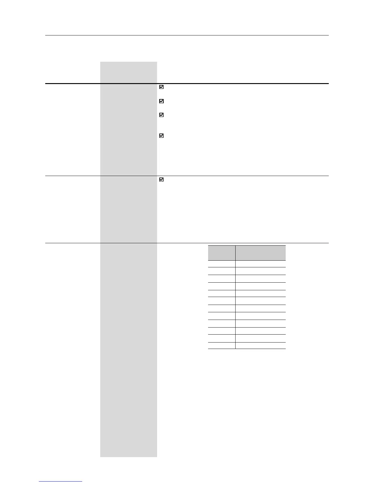
P295
(1)
300...311
Rated Inverter [ According to the
Current (I
nom
) rated inverter
current I
nom
) ]
-
P295
300
301
302
303
304
305
306
307
308
309
310
311
Rated Inverter
Current (I
nom
)
1.0A
1.6A
2.6A
2.7A
4.0A
4.3A
6.5A
7.0A
7.3A
10A
13A
16A