34
INSTALLATION
3
When installing the signal and control wiring, please note
the following:
Cable cross-section: 0.5...1.5mm
2
;
Relays, contactors, solenoid valves or breaking coils
installed near to Soft-Starters can generate interferences in
the control circuit. To eliminate this, you must install RC
supressors connected in parallel with the coils of these device,
when fed by alternate current and free wheel diodes when
fed by direct current.
When an extern HMI is used, the connection cable to the
Soft-Starter should be passed through the slot at the bottom
of the Soft-Starter.This cable must be laid separate from the
other cables existing in the installation, maintaining a
distance of 100mm (3.94in) each other.
Max. recommended torque in the terminals X2 and X1:
Maximum 0.5 Nm or 4.5lb.in.
The control wiring (X2:1...9) must be laid separate from
the power wiring.
The fans connections must be done through X7:1 and X7:2
connector, according to the voltage defined by the Soft-Starter
code:
Ex.: SSW-03. 205/220-440/
Electronic / fan voltage:
1 = 110Vac
2 = 220Vac
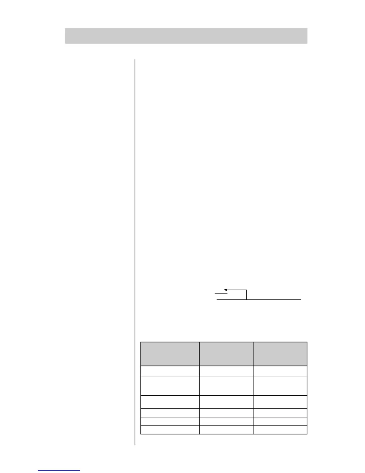
3.2.4 - FAN
CONNECTIONS
- PL
SSW-03 Plus Nominal current Nominal current
Type from the fans from the fans
(110V) (220V)
250mA 120mA
480mA 240mA
120A, 170A, 205A
255A, 290A, 340A,
410A
475A, 580A
500mA 240mA
750mA 360mA
1400mA 700mA
N.A. 840mA
670A
800A, 950A
1100A, 1400A
Table 3.3 - Fans consumption
 Loading...


