32
INSTALLATION
3
The signal (digital inputs/outputs output by relay) are
performed through the following connectors of the Control
Board CCS2.0X (see location in Figure 2.3, page 17).
X1 : Electronics supply (144mA for 110Vac; 78mA for
220Vac)
X2 : Digital and analog signals, output by relay
X7 : Connection to FAN.
XC2 : Connection to serial communication
XC6 : Connection to HMI-3P
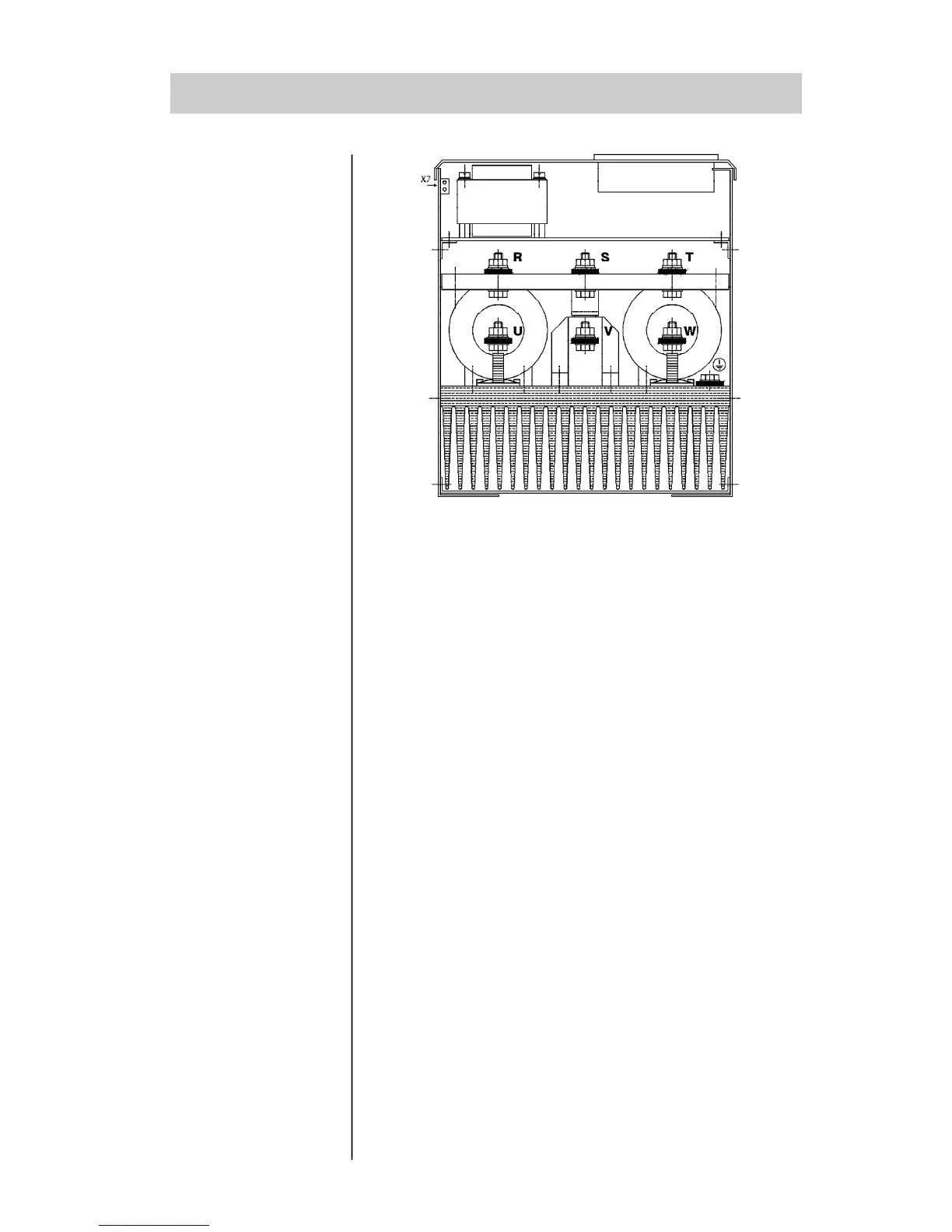
3.2.2 - Location of the
power/grounding/
fans connection
Figure 3.7 - Location of the power/grounding connection
3.2.3 - Signal and
Control
Connections
 Loading...


