86
6
DETAILED PARAMETER DESCRIPTION
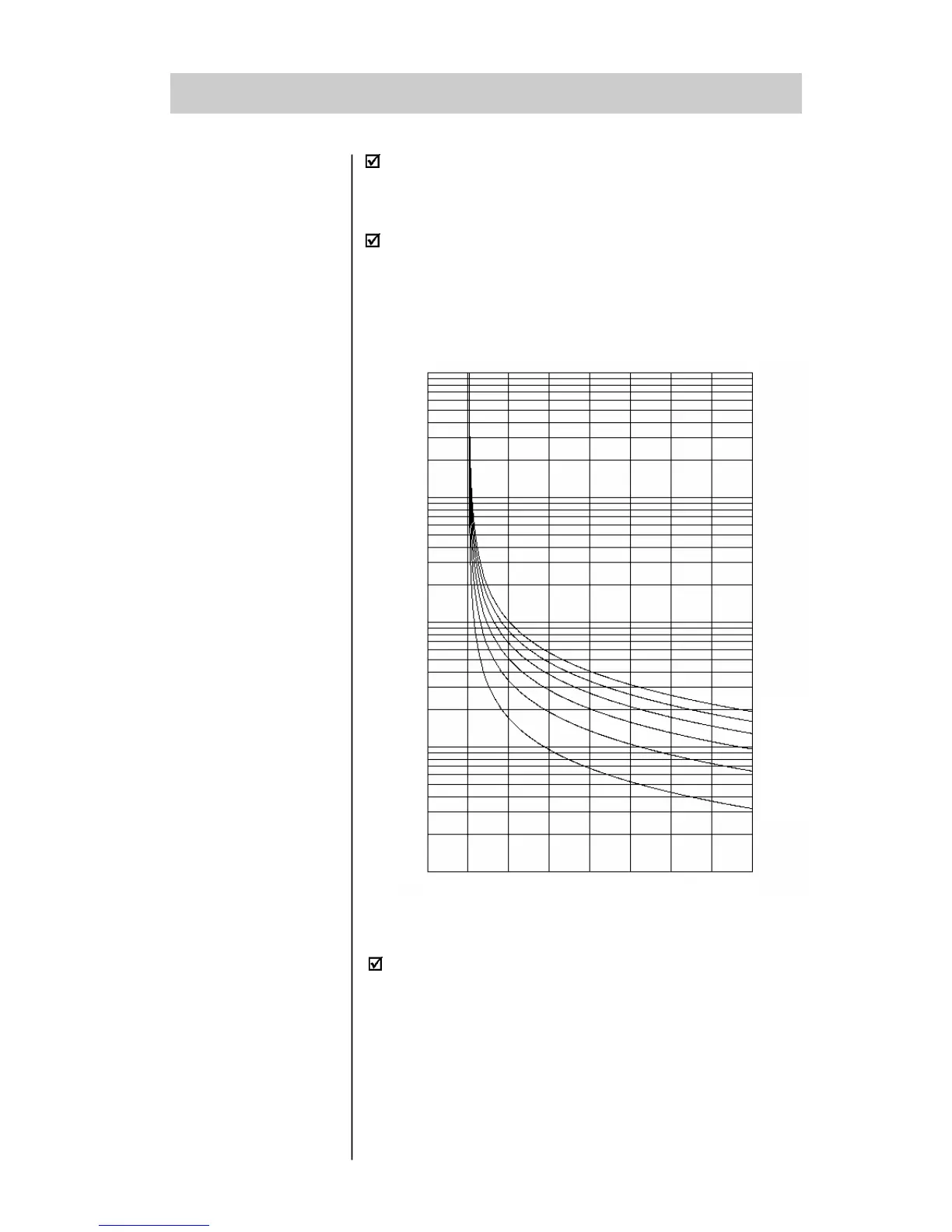
Figure 6.10 - Thermal Classes for Cold Motor Protection
Class 30
Class 25
Class 20
Class 15
Class 10
Class 5
0 1 2 3 4 5 6 7 8
10000
1000
100
10
1
If a Service Factor different from 1.00 is used, the nomi-
nal current for the chart (figure 6.10) has to be
corrected by the S.F. For example: a motor of In=100A
and S.F.=1.15 has 1 x In=115A.
t (s)
x In
The cooling time of the thermal image depends on the
motor power, i. e., for each power, a different cooling
time is considered. If a different cooling time is required,
this setting can be made at P27.
The estimated value for the motor temperature is saved
in non-volatile memory always the control board is
switched off. Thus, always the control board is switched
on, the last saved value will be returned.
 Loading...


