SERVICING
Piston and Connecting Rod
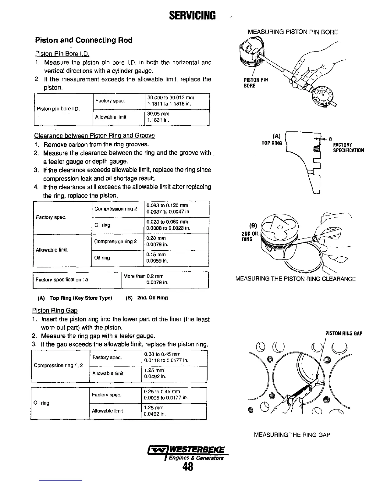
Piston Pin Bore I.D.
1.
Measure the piston
pin
bore I.D.
in
both the horizontal and
vertical directions with a cylinder gauge.
2.
If
the
measurement exceeds the allowable limit, replace the
piston.
Factory
spec.
30.000 to 30.013
mm
1.1811 to 1.1816
in.
Piston
pin
bore
I.D.
Allowable
limit
30.05
mm
1.1831 in.
Clearance between Piston Ring and Groove
1.
Remove carbon from the ring grooves.
2.
Measure the clearance between the ring and the groove with
a
feeler gauge or depth gauge.
3.
If
the
clearance exceeds allowable limit, replace the ring since
compression
leak and oil shortage result.
4.
If the clearance still exceeds the allowable limit after replacing
the ring, replace the piston.
Compression
ring
2
0.093 to 0.120 mm
0.0037 to 0.0047 in.
Factory spec.
0.020
to
0.060 mm
Oil
ring
0.0008 tq 0.0023 in.
Compression
ring
2
0.20 mm
0.0079 in.
Allowable limit
Oil
ring
0.15 mm
0.0059 In.
Factory
specification:
8
I More than 0.2 mm
0.0079 in.
(A) Top
Ring
(Key
Store
Type)
(B) 2nd,
011
Ring
Piston Ring Gap
1.
Insert the piston ring into the lower part of the liner (the least
worn out part) with the piston.
2.
Measure the ring gap with a feeler gauge.
3.
If the gap exceeds the allowable limit, replace the piston ring.
Factory
spec.
0.30 to 0.45
mm
O.Ot
18 to 0.0177 in.
Compression
ring
1 . 2
Allowable
limit
1.25
mm
0.0492
in.
Factory
spec.
0.25 to 0.45
mm
0.0098 to 0.0177 in.
Oil
ring
Allowable
limit
1.25
mm
0.0492
in.
...v
WESTERBEKE
Engines & Generators
48
MEASURING
PISTON
PIN
BORE
I
PISTON
PIN
BORE
(A)
TOP
RING
a
FACTORY
SPECIFICATION
MEASURING THE PISTON RING CLEARANCE
PISTON
RING
GAP
MEASURING THE RING GAP