SERVICING
Oil Clearance between Piston
Pin
and Small
End
Bushing
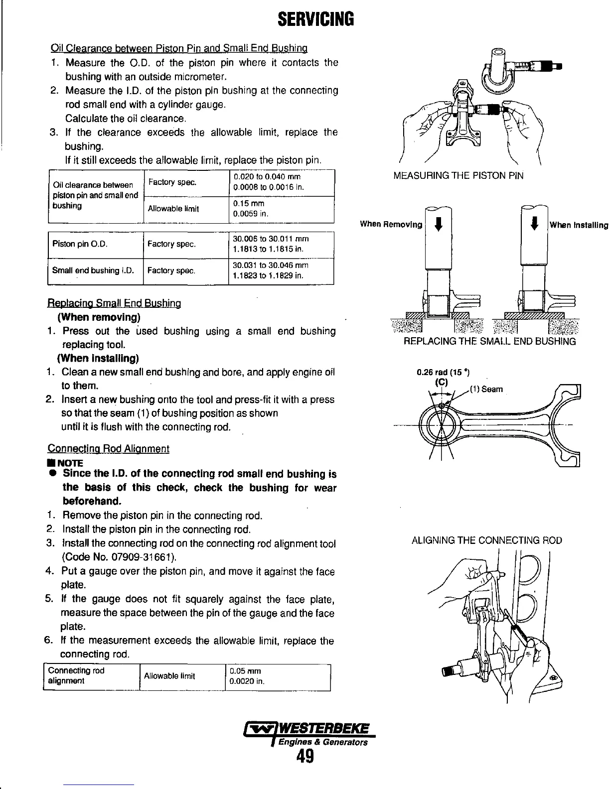
1.
Measure the
0.0.
of the piston
pin
where it contacts the
bushing with
an
outside micrometer.
2.
Measure the
1.0.
of the piston pin bushing
at
the connecting
rod
small end with a cylinder gauge.
Calculate the oil clearance.
3.
If the clearance exceeds the allowable limit, replace the
bushing.
If it still exceeds the allowable limit, replace the piston
pin.
Factory
spec.
0.020
to
0.040
mm
Oil clearance between
0.0008
to
0.0016
in.
piston pin
and
small
end
bushing
Allowable limit
O.15mm
0.0059
in.
MEASURING
THE
PISTON
PIN
When Removing "
Installing
Piston pin
0.0.
Factory spec.
Small end bushing 1.0. Factory
spec.
Replacing Small End Bushing
(When removing)
30.006 to
30.011
mm
1.1813to 1.1815
in.
30.031
to
30.046
mm
1.1823
to
1.1829
in.
1. Press out the used bushing using a small end bushing
replacing tool.
(When installing)
1. Clean a new small end bushing and bore, and apply engine oil
to them.
2.
Insert a new bushing onto the tool and press-fit it with a press
so that the seam (1) of bushing position
as
shown
until it is flush with the connecting
rod.
Connecting
Rod
Alignment
•
NOTE
• Since the
1.0.
of
the connecting rod small end bushing is
the basis of this check, check the bushing for wear
beforehand.
1.
Remove the piston pin
in
the connecting rod.
2.
Install the piston pin
in
the connecting
rod.
3. Install the connecting
rod
on
the connecting
rod
alignment tool
(Code
No.
07909-31661).
4. Put a gauge over the piston pin, and move it against the face
plate.
5.
If
the gauge does not fit squarely against the face plate,
measure the space between the pin of the gauge and the face
plate.
6. If the measurement exceeds the allowable limit, replace the
connecting
rod.
Connecting rod
alignment
Allowable limit
O.05mm
0.0020
in
.
.....
WESTERBEKE
Engines & Generators
49
REPLACING
THE
SMALL
END
BUSHING
0.26 'ad (15
')
(e)
(1) Seam
ALIGNING
THE
CONNECTING
ROD