Aufstellung de
Einbau- und Betriebsanleitung Wilo-Control EC/ECe-Booster 13
6.5.1 Übersicht der Bauteile: Wilo-Con-
trol EC-Booster
F1 F2 F3
1 2 3 4 5 6 7 8 9 10 11 12 13 14 15 16 17 18
19 20 21 22 23 24 25 26 27 28 29 30 31 32 33 34 35 36
37 38 39 40 41 42 43 44 45 46 47 48 49 50 51 52 53 54
T1
1 3 5 13 A1
2 4 6 14 A2
T2 T3
L1 L2 L3 NO
T1
1 3 5 13 A1
2 4 6 14 A2
T2 T3
L1 L2 L3 NO
GND A(+) B(-)
GND LO
J4
J3
J2
HI
1
2
26
Current Pump1
Current Pump2
4
5
8
9
6
3
2
1
7
10
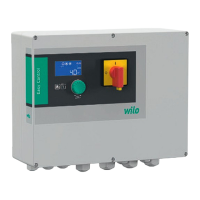
Fig.2: Control EC-B 2...
1 Klemmleiste: Netzanschluss
2 Einstellung Netzspannung
3 Klemmleiste: Erde (PE)
4 Klemmleiste: Steuerung/Sensorik
5 Schützkombinationen
6 Ausgangsrelais
7 Steuerplatine
8 Potentiometer für Motorstromüberwachung
9 ModBus RTU: RS485-Schnittstelle
10 ModBus RTU: Jumper für Terminierung/Polarisation
PE
COM
230
380
400
F1 F2 F3
T1
2 4 6 14 A2
T2 T3
F4 F5 F6
T1
2 4 6 14 A2
T2 T3
T1
2 4 6 14 A2
T2 T3
1
2
26
Current Pump1
Current Pump2
2
3
24 2
5
2
6
27 2
8
2
9
30 3
1
3
2
33 3
4
35 36 3
7
3
8
3
9
4
0
41 42 4
3
44 4
5
4
6
47 4
8
4
9
50 5
1
5
2
53 5
4
1 2
3
4
5 6
7
8
9
1
0
11 12 1
3
14 1
5
1
6
17 1
8
1
9
2
0
21 22
Current Pump3
A(+)
B(-)
GND
55
58
56 57 59 62 676564 6660 61 63
68
1 ON
L!
L3L2
T1
T3T2
0
OFF
1
2
26
J4
J3
J2
4
4
5
8
9
6
3
2
1
7
10
11
4
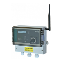
Fig.3: Control EC-B 3...
1 Hauptschalter/Netzanschluss
2 Einstellung Netzspannung
3 Klemmleiste: Erde (PE)
4 Klemmleiste: Steuerung/Sensorik
5 Schützkombinationen
6 Ausgangsrelais
7 Steuerplatine
8 Potentiometer für Motorstromüberwachung
9 ModBus RTU: RS485-Schnittstelle
10 ModBus RTU: Jumper für Terminierung/Polarisation
11 Gehäusedeckel
 Loading...