en Installation
58 WILO SE 2019-07
L1 L2
3~ 50/60 Hz
L
1~ 50/60 Hz
L3
N
com
230
380
400
1
2
3
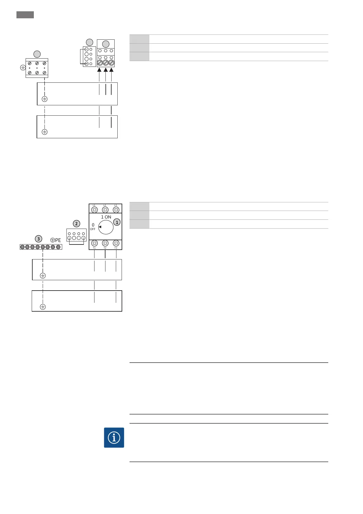
Fig.6: Mains connection Wilo-Control EC-B
1.../EC-B 2...
1 Terminal strip: Mains connection
2 Mains voltage adjustment
3 Terminal strip: Earth (PE)
Mains connection 1~230V:
▪Cable: 3-core
▪Wire: L, N, PE
▪Mains voltage adjustment: Converter bridge 230/COM
Mains connection 3~230V:
▪Cable: 4-core
▪Wire: L1, L2, L3, PE
▪Mains voltage adjustment: Converter bridge 230/COM
Mains connection 3~380V:
▪Cable: 4-core
▪Wire: L1, L2, L3, PE
▪Mains voltage adjustment: Converter bridge 380/COM
Mains connection 3~400V:
▪Cable: 4-core
▪Wire: L1, L2, L3, PE
▪Mains voltage adjustment: Converter bridge 400/COM (factory setting)
Insert the connection cable laid by the customer through the threaded cable glands and
secure. Connect the wires to the main switch as per the connection diagram.
L1 L2
3~ 50/60 Hz
L
1~ 50/60 Hz
L3
N
com
230
380
400
Fig.7: Mains connection Wilo-Control EC-B 3...
1 Main switch
2 Mains voltage adjustment
3 Terminal strip: Earth (PE)
Mains connection 1~230V:
▪Cable: 3-core
▪Wire: L, N, PE
▪Mains voltage adjustment: Converter bridge 230/COM
Mains connection 3~230V:
▪Cable: 4-core
▪Wire: L1, L2, L3, PE
▪Mains voltage adjustment: Converter bridge 230/COM
Mains connection 3~380V:
▪Cable: 4-core
▪Wire: L1, L2, L3, PE
▪Mains voltage adjustment: Converter bridge 380/COM
Mains connection 3~400V:
▪Cable: 4-core
▪Wire: L1, L2, L3, PE
▪Mains voltage adjustment: Converter bridge 400/COM (factory setting)
6.5.4 Switchgear mains connection:
Control ECe-Booster
CAUTION
Risk of material damage due to incorrectly set mains voltage!
The switchgear can be operated at different mains voltages. However, the control
voltage must always be 230V. For this reason, the cable jumper is set to the correct
mains voltage at the factory. Do not change the cable jumper! If the wrong mains
voltage is set, the controls will be destroyed!
NOTICE
Neutral conductor required
A neutral conductor is required at the mains connection for the correct functioning
of the controls.
Insert the connection cable laid by the customer through the threaded cable glands and
secure. Connect the wires to the main switch as per the connection diagram.
 Loading...