42 3064298_201805
Indoormoduleelectricalconnection
22.3 PSU/PV/SmartGrid/ODUbusconnection
(See also "Additional functions" chapter.)
230V~
X1
WP025 = ON
Smart*
Grid
SG0
9
10
SG1
11
12
WP025 = OFF
Power-
OFF
9
10
PV*
increase
11
12
ODU X1
ODU
bus
BWL-1S(B)
05/07/10/14/16
C2 13
C1 14
* Floating contacts
Electric heater
feed
Output 3way DV
heating/DHW
X1
10
9
12
11
14
13
16
15
ODU bus
(2x0.75 mm
2
, screened)
Power-OFF,
PV / Smart Grid
GTS (appliance type connector)
X
Notes:
− For systems that can be temporarily blocked/shut down by the power supply utility (power-OFF), a
correspondingswitchingsignal(oatingcontact)oftheenergysupplyutilitymust be connected to
terminal X1-9/10 in order to signal the power-OFF period to the control unit of the BWL-1S(B).
− If the power-OFF function is not used, insert a jumper at terminal X1-9/10.
− The electrical connection of the Smart Grid and power-OFF function must be made in accordance with the
stipulations of the local power supply utility.
Example1:Powersupplywithpower-OFF,withouton-siteloaddisconnection
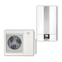
Outdoor module
(ODU)
Indoor module
(IDU)
2
BWL-1S(B)-05/07/10/14/16
230 V/400 V
On-site
connections
ODU bus
X1-9/10
(power-OFF)
Control 230 V/50 Hz
Electric heater 230 V/400 V/50 Hz
Outdoor module 230 V/400 V/50 Hz
Ripple control receiver
(floating contact)
3
3/5
3/5