3064298_201805 79
Systemcongurations
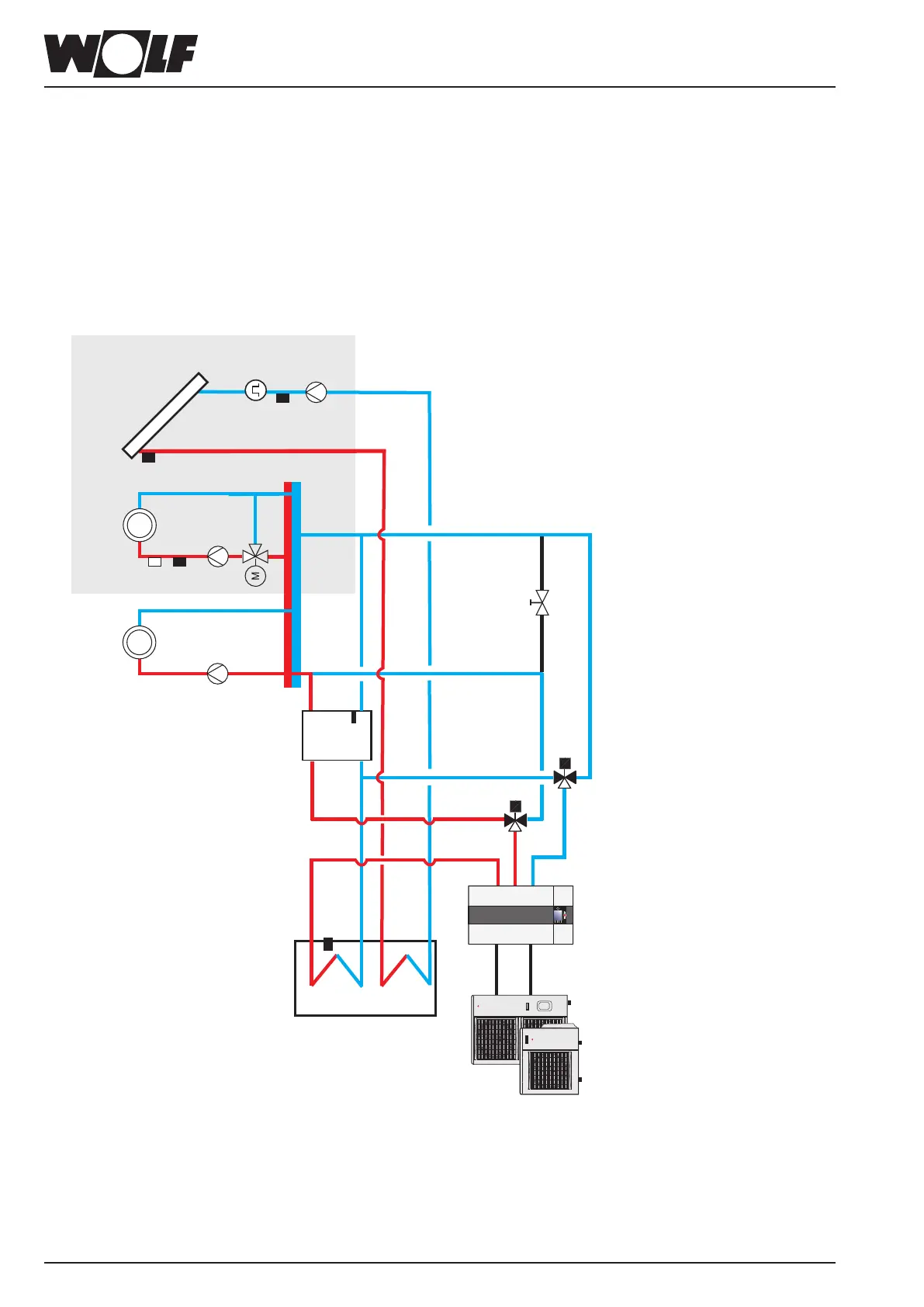
29.2.8 Systemconguration15
BWL-1S(B)
●Splitair/waterheatpump
●Separatingcylinder
●SolarDHWcylinder
●Heatingcircuit
●CircuitwithmixerextensionwithMM
●SolarcircuitextensionwithSM1/SM2
●DHWheating
●Activecoolingpossible
SFK
SKP
DFG
RLF
Separating cylinder
Heating circuit
HCP
Circuit with mixer
MCP
MaxTh
VF
MM
With indoor module
3-way diverter valve
for heating/DHW and
feed/heating circuit pump
integral
Indoor module
Outdoor module
Solar DHW cylinder
Please note:
Header temperature sensor SAF must be
installed in the return area of the low loss
header or separating cylinder.
SAF
Extension options
3-way diverter valve
heating/cooling
3way DV HTG/
Cooling
SFS
SF
Important information:
In this schematic diagram, shut-off valves, air vent valves and safety equipment are not fully represented.
These should be provided for each system individually, in line with the applicable standards and regulations.
Hydraulic and electrical data can be found in the hydraulic system solutions technical guide.