3064298_201805 47
Indoormoduleelectricalconnection
22.6 Electricalconnection(lowvoltages)
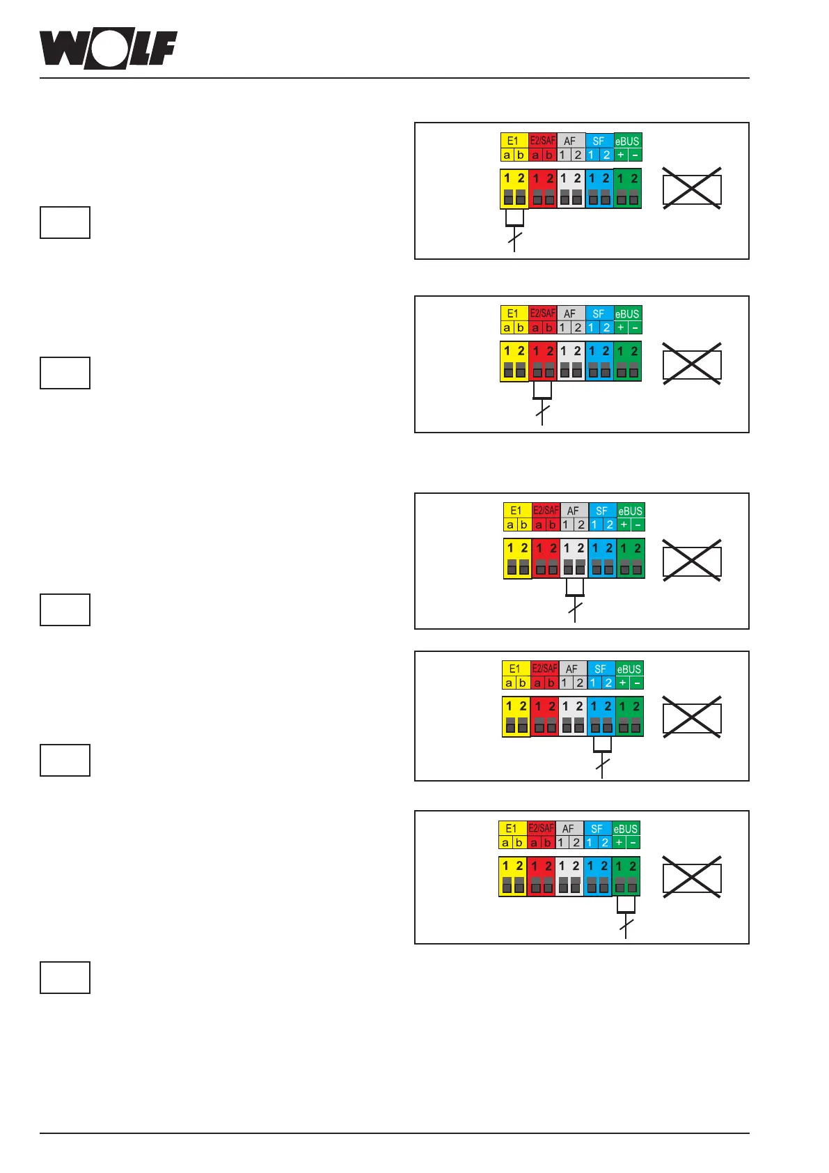
ConnectinginputE1
Push connecting cable through cable entry.
Connect the connection cable for input E1 to terminals E1.
No external voltage may be connected to input
E1, as this could destroy the component.
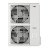
ConnectinginputE2/SAF
Push connecting cable through cable entry.
Connect the connection cable for input E2/SAF to terminals
E2/SAF.
Only one external voltage of max. 10 V may
be connected to input E2/SAF, otherwise the
PCB will be destroyed.
1(a) = 10 V, 2(b) = GND
5 k NTC header sensor SAF; alternatively 0-10 V or floating
contact
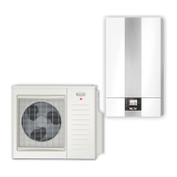
Connectingtheoutsidesensor
The outside sensor can be connected to the terminal strip
of the heat pump at connection AF, or to the terminal strip
of the control accessories.
No external voltage may be connected to input
AF, as this will destroy the component.
Connectingthecylindersensor
Push connecting cable through cable entry.
Connect the lead for the SF cylinder sensor to the
SF terminals.
No external voltage may be connected to input
SF, as this will destroy the component.
ConnectingdigitalWOLFcontrolaccessories
(e.g.BM-2,MM,KM,SM1,SM2)
Only controllers from the WOLF range of accessories may
be connected. Each accessory is supplied with its own
connection diagram.
Use a two-core cable (cross-section > 0.5 mm²) as the
connecting cable between the control accessory and the
BWL-1S (1 is + and 2 is -).
When installing the appliance in places where
there is a risk of increased electromagnetic
interference, it is advisable to fit screened
sensor leads and eBUS cables. The cable
shield should be connected at one end to the
PE potential in the control unit.
230V~
2
Figure: Input E1 connection
Please
note
230V~
2
Figure: Input E2/SAF connection
Please
note
230V~
2
Figure: Outside sensor AF connection
Please
note
230V~
2
Figure: Cylinder sensor SF connection
Please
note
230V~
2
Figure: Connecting digital WOLF control accessories (eBUS interface)
Please
note