82 3064298_201805
Systemcongurations
29.2.11 Systemconguration51
BWL-1S(B)
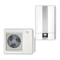
●Splitair/waterheatpump
●0-10Vactivation(atinputE2/SAF)
●Activecoolingpossible
0 - 10 V
SF
U
= 0…10 V at input E2/SAF:
0V ≤ U< 1.2V → heatpumpOFF
1.2V≤ U ≤ 4.0V → 0-100%compressorcoolingmode (1...12%→12%)
(13...100%→13...100%)
4.2V≤ U ≤ 7.0V → 0-100%compressorheatingmode (1...12%→12%)
(13...100%→13...100%)
7.2V≤ U ≤ 10.0V
→
100 % compressor heating mode
+ 0-100 % elec. heater, heating mode
(1...20%→20%)
(21...80%→21...80%)
(81...100%→100%)
Notes:
- Application limits: Compressor T_FL/T_RTN = 55 °C, elec. heater T_FL = 75 °C
- Enable electric heater for heating mode (WP090 = ON)
- CongureoutputA1todefrost(WP003=Defrost)
→ Indefrostmode,outputA1isswitched
in order to display defrost mode to the BMS.
- Ensure max. compressor starts per hour by BMS
- Ensuremax.owtemperaturebyBMS
- Connect dew point monitor or jumper to input E1
- Ensure dew point monitoring by BMS if required
Externaldemand/controlby
buildingmanagementsystem(BMS)
DHWheatingmodeforsystem
conguration51
Inthissystemconguration,theappliancecancarryoutDHWheat-upautomatically
on demand. DHW heat-up mode has priority over BMS mode.
DHWheat-upmodecanbesuppressedinsystemconguration51byremoving
the SF cylinder sensor, carrying out a parameter reset and resetting the system
conguration.
In this case, disconnect integral 3-way diverter valve for HTG/DHW.
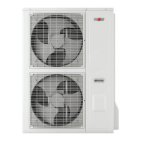
A 3-way diverter valve for
central heating/DHW and a
feed/heating circuit pump
are integrated into the
indoor module
Indoor moduleOutdoor module
Important information:
In these schematic diagrams, shut-off valves, air vent valves and safety equipment are not fully represented.
These should be provided for each system individually, in line with the applicable standards and regulations.
Hydraulic and electrical data can be found in the hydraulic system solutions technical guide.