Service Parts Disassembly
Xerox Internal Use Only Phaser 6600 and WorkCentre 6605
Service Manual
4-47
Xerographic
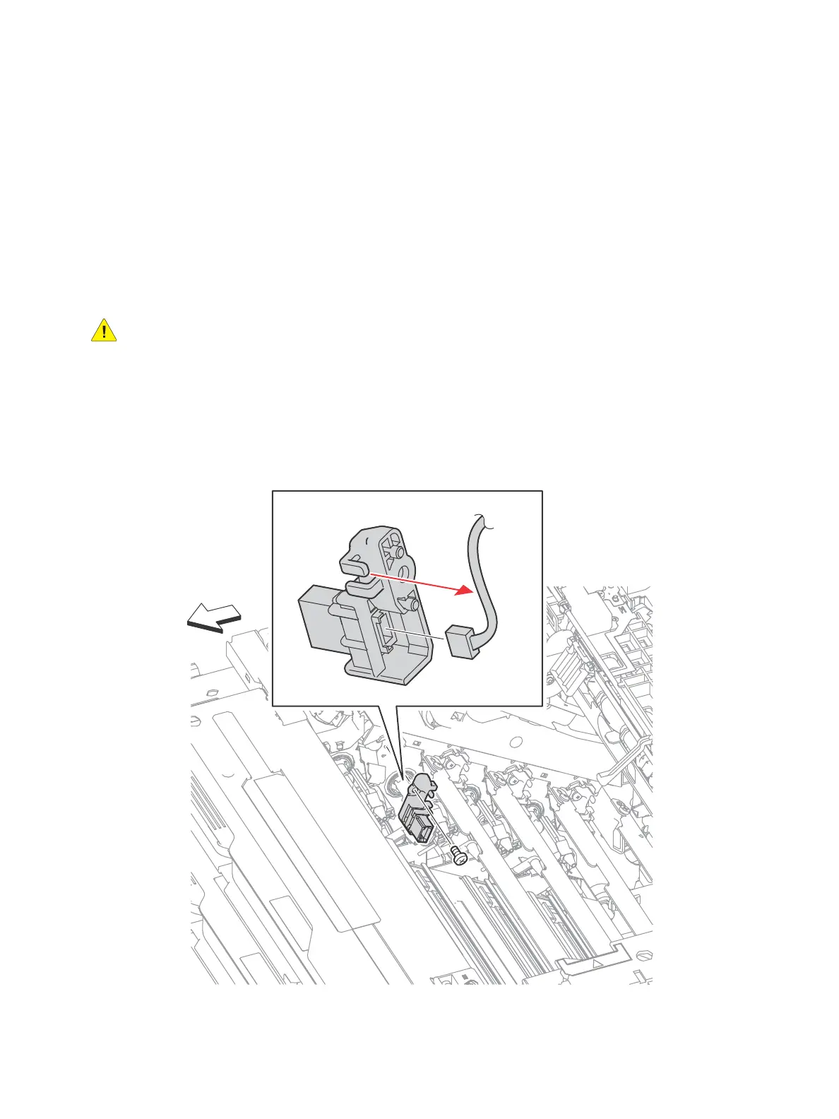
Transfer CRUM Connector Assembly
PL8.1.1
Note: Since the removal procedure is common among the four Transfer CRUM Connector
Assemblies (PL8.1.1), this section describes only the removal procedure of the Transfer CRUM
Connector Assembly connected to the Imaging Unit Y.
WARNING: The Fuser is very hot. Take added care when handling the fuser to avoid being burned.
1. Remove the Transfer Belt Assembly. (page 4-38)
2. Remove the Imaging Units Y, M, C, K. (page 4-48)
3. Remove the Top Cover Assembly. (SFP page 4-115; MFP page 4-118)
4. Remove the screw (silver, 6mm) that attaches the Transfer CRUM Connector Assembly.
5. Release the harness from the harness guide on the Transfer CRUM Connector Assembly, unplug
the connectors and remove the Transfer CRUM Connector Assembly.

 Loading...


