Service Parts Disassembly
Xerox Internal Use Only Phaser 6600 and WorkCentre 6605
Service Manual
4-135
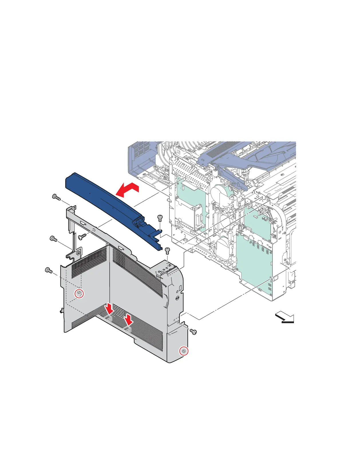
4. Remove the screw (silver, 6mm) that attaches the Top Left Cover to the printer, and slide the cover
to the rear and out to remove it. Allow the harness for the Control Panel to feed through the hole
in the cover.
5. Remove the two screws (silver, 6mm) and the one screw (silver, tapping, 8mm) that attach the Left
Cover Assembly at the rear.
6. Remove the screw (silver, tapping, 8mm) that attaches the Left Cover Assembly at the top on the
side above the IP Board Cover.
7. Remove the screw (silver, 6mm) that attaches the Left Cover Assembly at the top near the front.
8. Remove the screw (silver, 6mm) that attaches the front of the Left Cover Assembly.
9. Release the boss on the bottom front of the Left Cover Assembly, release the two hooks below the
recessed grip using a flatblade screwdriver or the like while flexing the front end slightly outward,
and then release the boss on the rear end.

 Loading...


