KCU116 Board User Guide 50
UG1239 (v1.2) September 28, 2018 www.xilinx.com
Chapter3: Board Component Descriptions
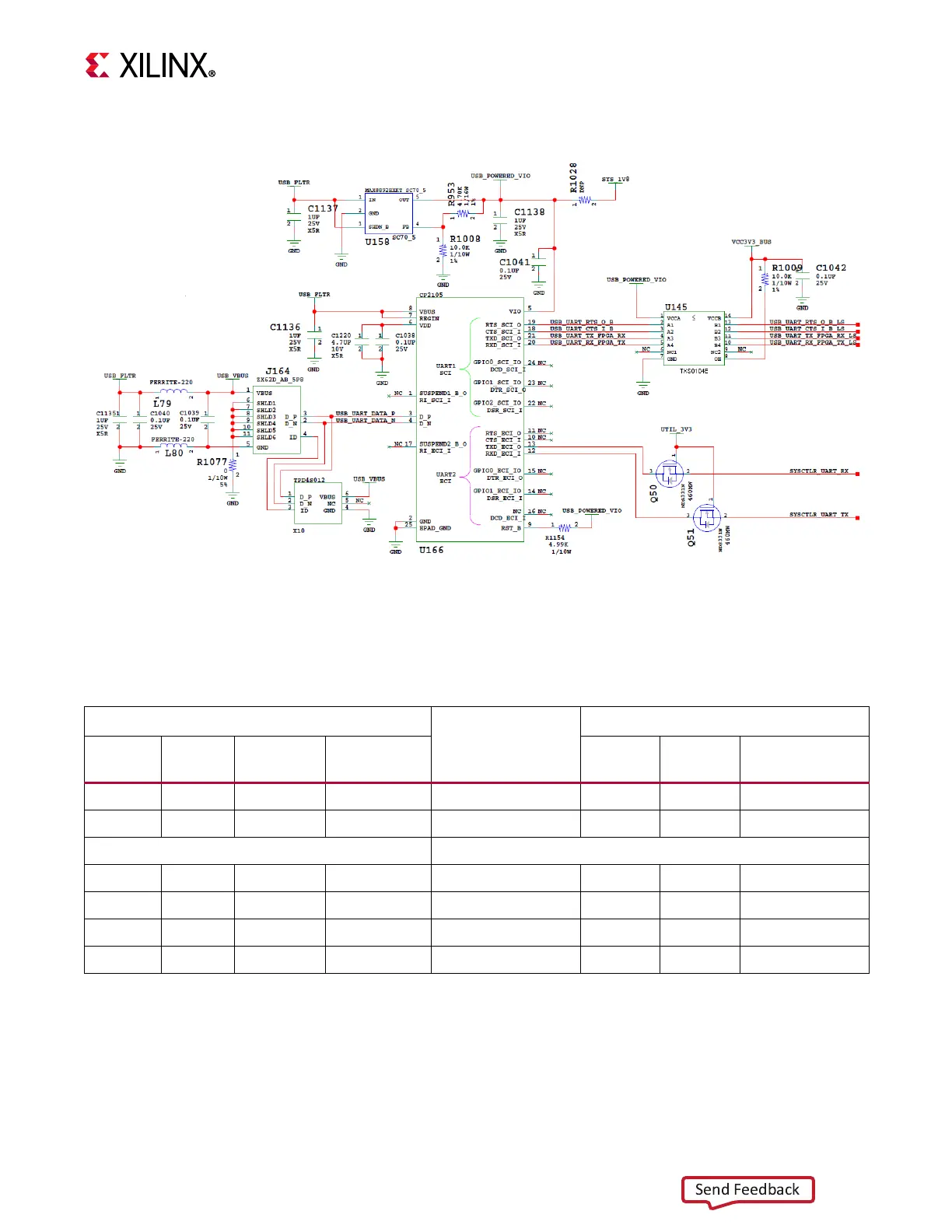
The Silicon Labs CP2105GM dual USB-to-UART bridge circuit is shown in Figure 3-17.
Table 3-14 lists the CP2105GM connections to FPGA U1. The USB UART schematic nets are
named from the perspective of the CP2105GM device (U166).
X-Ref Target - Figure 3-17
Figure3‐17: KCU116 Dual UART CP2105GM
Table3‐14: FPGA U1 to CP2105GM U166 Connections
XC7Z010 SoC (U161)
Schematic Net
Name
CP2105GM Device (U166)
FPGA U1
Pin
Function Direction I/O Standard Pin Function Direction
C12 TX Output LVCMOS18 SYSCTLR_UART_TX 12 RXD Input
B15 RX Input LVCMOS18 SYSCTLR_UART_RX 13 TXD Output
XCKU5P FPGA (U1)
W12 RX Input LVCMOS18 USB_UART_TX 21 TXD Output
W13 TX Output LVCMOS18 USB_UART_RX 20 RXD Input
Y13 CTS Output LVCMOS18 USB_UART_CTS 18 CTS Input
AA13 RTS Input LVCMOS18 USB_UART_RTS 19 RTS Output