KCU116 Board User Guide 55
UG1239 (v1.2) September 28, 2018 www.xilinx.com
Chapter3: Board Component Descriptions
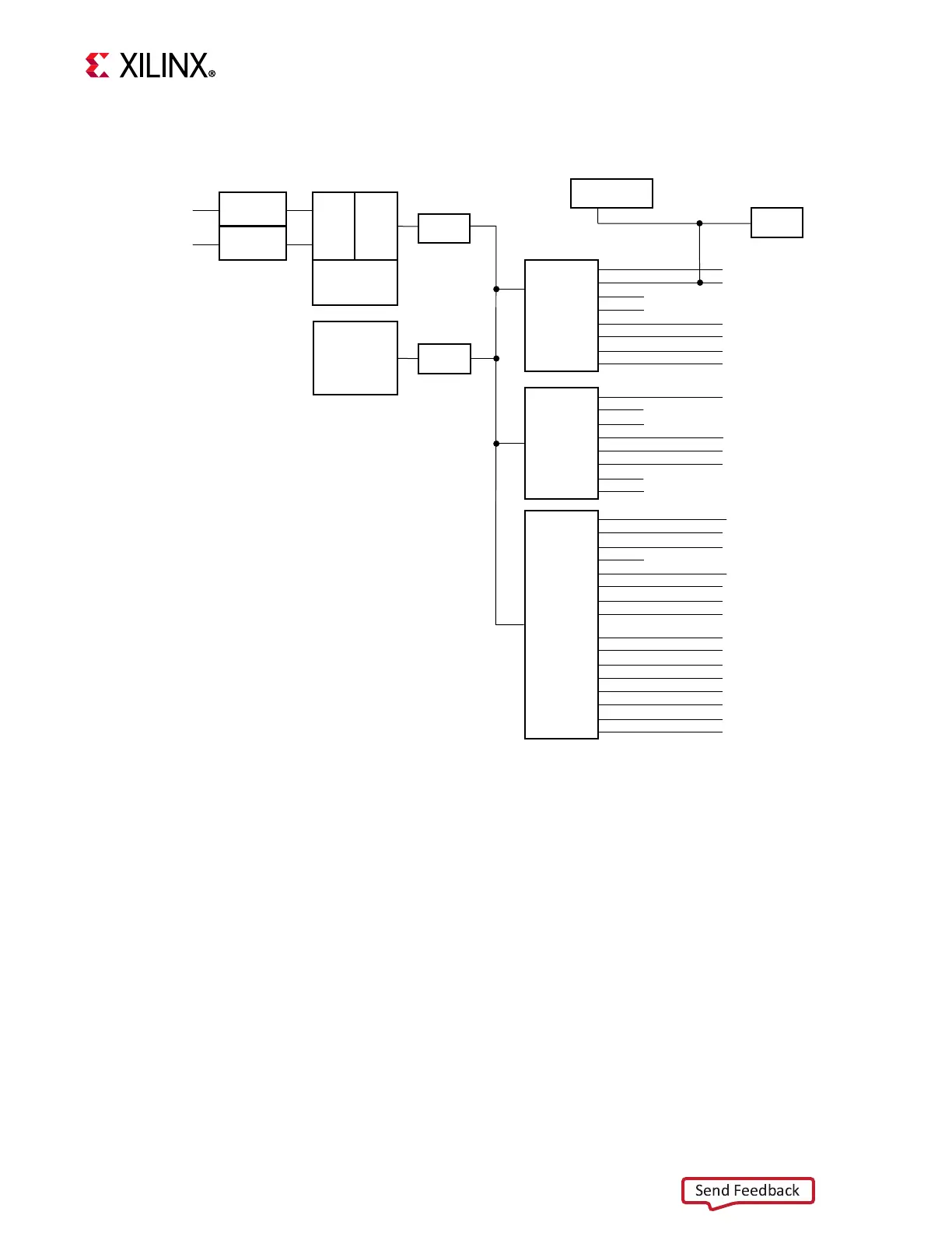
The KCU116 evaluation board I
2
C bus topology is shown in Figure 3-19.
X-Ref Target - Figure 3-19
Figure3‐19: I
2
C Bus Topology
Level
shifters
MAXIM_CABLE_B
Always
enabled
PMBUS_ALERT
UTIL_3V3 to SYS_1V8
U168
BANK
34
BANK
501
SYS Controller
U161
IIC MUX
TCA9548
U135
0x75
FMC_HPC0
MAXIM_PMBUS
NC
NC
ZSFP3
ZSFP2
ZSFP1
ZSFP0
0xx##
0x12-0x18,0x1A,0x72,0x73
0x50
0x50
0x50
0x50
Maxim power
regulators
Maxim
cable
IIC MUX
TCA9548
U34
0x74
EEPROM
NC
NC
USER_MGT_S1570
SI5328
PL_PMBUS
NC
NC
0x50
0x68
0x40-0x47,0x4B
TCA6416
IIC GPIO
Port
Expander
U147
0x21
IIC_MUX_RESET_B
MGTRAVCC_EN
MGTRAVTT_EN
NC
PL_DDR4_VTERM_EN
NC
NC
NC
PL_PMBUS_ALERT
MAXIM_PMBUS_ALERT
IIC_EXPANDER_GPIO
FMC_HPC0_PRSNT_M2C_B
NC
NC
NC
NC
0x5D
BANK 84
IIC_MAIN
U164
Level
shifter
Level
shifter
U163
U162
FPGA U1
J84
X18423-042618