YD-EM279
23
PREMIUM E-MOBILITY
●
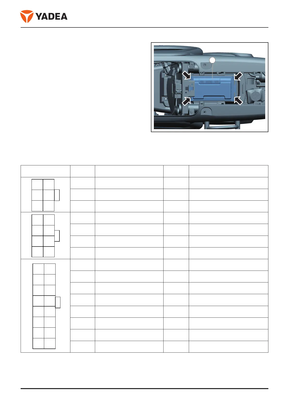
Disconnect the other wiring harnesses of the
controller.。
●
Dismantle unload bolt - arrow -.
●
Disassembly the controller - 1 -.
Installation
Installation is carried out in reverse order of disassembly.
3.2.4.4 Connector interface definition
Interface style Pin Function Pin Function
47
36
25
1 Hall signal (blue) 4 GND
2 Hall signal (green) 5 NC
3 Hall signal (yellow) 6 Hall - Power supply 4.3 V
1 ACC 5 High brake
2 Side brace signal 6 Throttle - GND
3 Throttle signal 7 Throttle - power supply 4.3 V
4 Gear signal 8 Backcart
1 T power 9 P-switch
2 Seat cushion detection signal 10 The instrument is one-wire pass
3 Low brake 11 Voice/speed alarm
4 Range extended mode 12 Lock the motor signal
5 Battery one-wire pass/charge 13 Turn the signal
6 Side-bracing power supply 14 Voltage selection
7 CAN_L 15 CAN_H
8 Throttle induction 16 GND
1
8
7
6
5
4
3
2
1
8 16
7 15
6 14
5 13
4 12
3 11
2 10
1 9
 Loading...