33
RX-V3300/DSP-AZ2
RX-V3300/DSP-AZ2
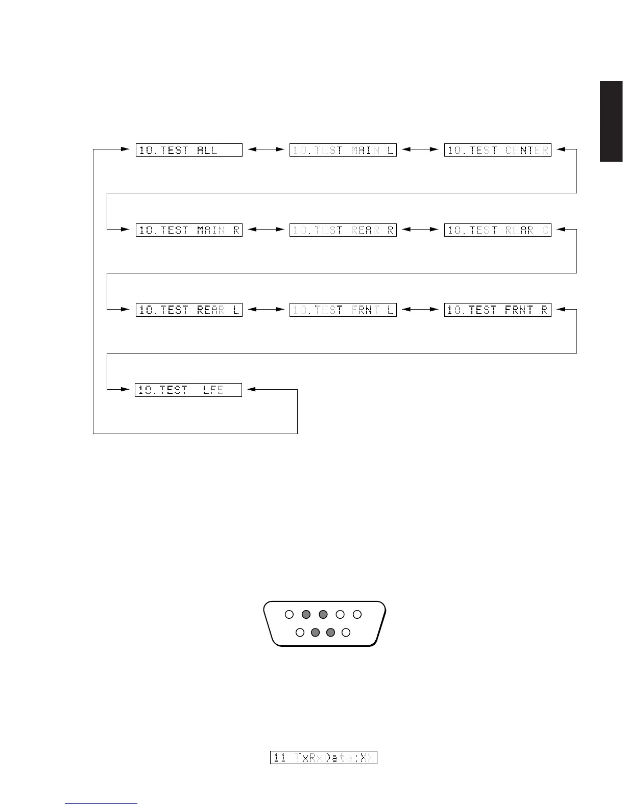
10. MANUAL TEST
The noise generator with a built-in DSP outputs the test
noise through the channels specified by the sub-menu.
The noise frequency for LFE is 35 to 250 Hz. Other than
that, the center frequency is 800Hz.
TEST ALL TEST MAIN L TEST CENTER
TEST MAIN R
TEST REAR R TEST REAR CENTER
TEST REAR L
Noise is output from all channels.
Noise is output from the MAIN L channel.
Noise is output from the CENTER
channel.
Noise is output from the MAIN R channel.
Noise is output from the REAR R channel.
Noise is output from the REAR C
channel.
Noise is output from the REAR L
channel.
TEST FRONTL
Noise is output from the FRONT L
channel.
TEST FRONT R
Noise is output from the FRONT R
channel.
TEST LFE
Noise is output from the SUB WOOFER
channel.
10.MANUALTEST
11. RS-232C
This menu is used to check transmission of the data
and the flow port of the hardware.
With the power turned off, short between pins No.2
(RxD) and No.3 (TxD), and between pins No.7 (RTS)
and No.8 (CTS) of the RS-232C terminal. (Be sure to
turn off the power when shorting the pins.)
Start DIAG and select the menu.
There are two sub-menu items.
11.RS-232C
TxD/RxD DATA
The sub-menu is used to check transmission of the test
data. “OK” appears when the data is transmitted properly
and “NG” when it is not.
In this mode, NULL command transmission is continued
after the test command is transmitted.
RxD
RTS CTS
TxD
123
6789
45
TxRxData