ABCDEFGH I J KL
RX-V3300/DSP-AZ2
77
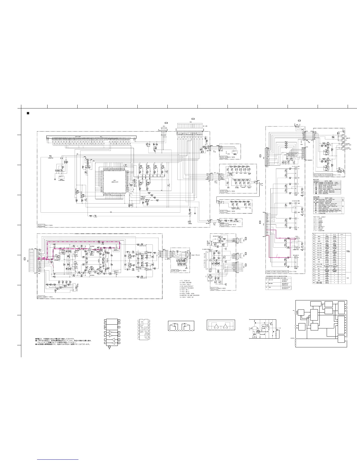
SCHEMATIC DIAGRAM (OPERATION)
1
2
3
4
5
6
7
8
9
★ All voltages are measured with a 10MΩ/V DC electric volt meter.
★ Components having special characteristics are marked s and must be
replaced with parts having specifications equal to those originally
installed.
★ Schematic diagram is subject to change without notice.
x: NOT USED
O:USED / APPLICABLE
52
Display
controller
Segment
digit
select/
output
circuit
Serial
receive
circuit
Digit
output
circuit
Clock
generator
DIG11/
SEG42
51
DIG12/
SEG41
50
DIG13/
SEG40
49
DIG14/
SEG39
48
DIG15/
SEG38
47
DIG16/
SEG37
46
DIG17/
SEG36
45
SEG35
XOUT
6
Vcc1
8
Vcc2
18
Vss
5
Vp
64
XIN
7
CS
SCK
3
SDATA
4
RESET
1
SEG00
44
9
SEG34
SEG26
17
19
SEG25
Segment
output
circuit
Display code
RAM
(8-bit x 60)
CGROM
(35 bit x 166)
CGROM
(35 bit x 16)
code
select
Code
write
Code/
command
control
circuit
DIG00
63
53
DIG10
IC901: M66003-0101FP
FL Display Driver
2
data
timing
clock
dot data
write
scan pulse
IC701: ADM202JRN-REEL7
RS-232 Driver/Receiver
1
3
2
16
C1+
C1–
Vcc
V+
11
14
T1in
T1out
+5V → +10V
Voltage Boost
Circuit
4
5
6
C2+
C2–
V–
+10V → –10V
Voltage Inverter
T1
10
7
T2in
T2out
T2
12
13
R1in
R1out
R1
9
8
15
R2in
R2out
GND
R2
IC801: TC4066BP
Quad Analog Switch/Multiplexer
1
2
3
4
5
6
7
IN/OUT1
OUT/IN1
OUT/IN2
IN/OUT2
CONT2
CONT3
VSS
14
13
12
11
10
9
8
VDD
CONT1
CONT4
IN/OUT4
OUT/IN4
OUT/IN3
IN/OUT3
87654321
OUT1
–Vcc
+IN2
–IN2
OUT2
+Vcc
–IN1
+IN1
IC802: NJM2068L-D
Dual OP-Amp
IC803: µPC4570HA
Dual OP-Amp
Vcc Vo
1
-Vm
1
+Vm
1
V
EE
+Vm
2
-Vm
2
Vo
2
Vcc
1234 567 89
++--
12
IC804: NJM4556AL
Dual OP-Amp
8
2, 6
3, 5
1, 7
4
V+
–INPUT
+INPUT
V–
OUTPUT
1
4
5
6
14
3
5
6
2
3
2
8
8
7
1
4
3
7
6
9
5
2
8
2
3
4
1
5
6
8
7
4
11
12
13
7
10
9
BASS EXTENSION
TONE
CONTROL
REC OUT
SELECTOR
PHONES
MUTE
FL DRIVER
FL DISPLAY
INPUT
SELECTOR
VOLUME
Page 76
to FUNCTION
D1
Page 80
to POWER (3)
G4
Page 76
to FUNCTION
I7
Page 78
to VIDEO (5)
I2
Page 80
to POWER (1)
I4
Page 78
to VIDEO (1)
E5 Page 76
to FUNCTION
B1 Page 75
to DSP
H5
-27.5
~
~
~
-34.4
-34.4
-34.4
-34.4
-34.7
~
~
~
~
~
~
~
~
~
~
~
~
~
~
~
~
~
~
~
~
~
~
~
~
~
~
~
~
~
~
~
~
~
~
~
~
~
~
~
~
~
~
~
~
~
~
~
~
~
~
~
~
~
~
~
~
~
~
~
~
~
~
-27.5
-27.5
-27.5
4.9
0
4.8
~
~
4.8
~
~
~
~
~
-34.7
00
-34.7
~
~
~
~
~
~
~
~
~
~
~
~
-34.6
-34.6
~
~
~
~
~
~
4.8
0
0
0
4.8
4.8
4.8
4.3
~
4.8
~
~
4.8
~
4.7
4.7
4.8
4.6
4.8
4.3
-34.4
4.8
-34.6
-34.4
4.8
-34.6
-34.4
4.8
-34.6
-27.9
-35.0
~
4.8
~
4.9
~
~
~
~
~
~
~
~
~
~
~
~
~
~
~
~
~
~
~
~
~
~
~
~
~
~
~
~
~
~
~
4.8
-34.6
-35.0
-8.5
8.5
0
0
0
0
0
0
0
-8.5
-8.5
0
0
0
0
-8.5
-8.5
-8.5
-11.8
11.4
0
0
0
-11.8
0
0
0.7
0
0
0.7
9.0
9.6
0
0
0
-9.4
0
0
0
9.0
0
0
0
0
0
0
-10.6
11.4
-9.4
0
8.5
8.5
0
MAIN L
0
4.1
4.1
4.8
4.8
3.5
0
0
0
0
0
0
0
11.4
11.4
11.4
11.4
4.9
11.4
11.1
10.8
0
0
4.9
11.4
11.1
10.8
4.9
0
4.8
4.9
0
-8.8
0
4.9
7.2
9.5
2.4
0
9.1
-9.3
0
-4.5
0
0
MAIN L
Page 80
to POWER (3)
I2
0.01/50
0.01/50