36
RX-V3300/DSP-AZ2
RX-V3300/DSP-AZ2
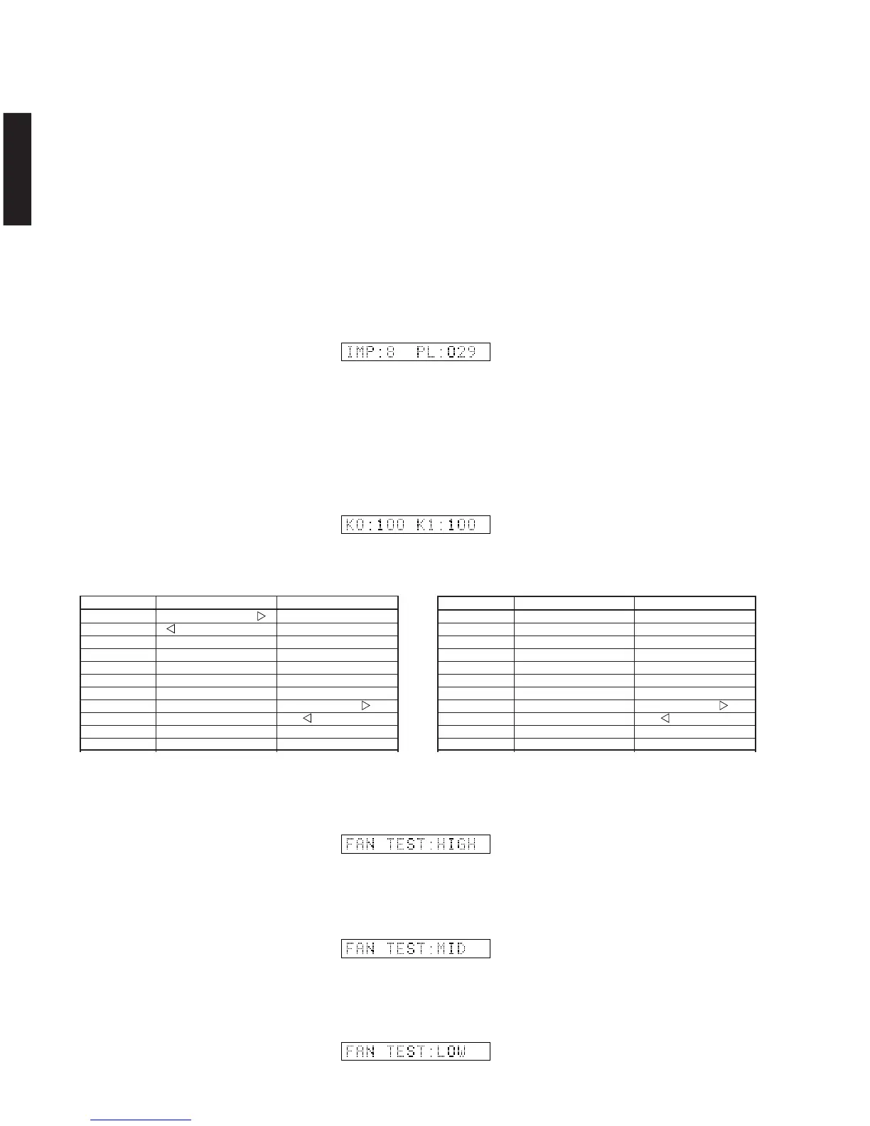
IMP SW/POWER LIMIT (Impedance/power limiter
detection)
IMP: 8 or 4 ohm impedance switch setting
PL: Power limiter detection value
The voltage value of pin No. 135 of IC520 is displayed,
using 5V/256 as standard.
When the power is turned on, the speaker impedance
switch setting is automatically detected, using the input
voltage value of pin No. 135 of IC520.
The output of ports No.60 and No. 61 are controlled by
using the input voltage value of pin No. 135 of IC520.
When higher than VthH, the port output is changed
from L to H.
When lower than VthH, the port output is changed from
H to L.
IMPSW/POWERLIMIT(インピーダンス/パワーリミッ
ターの検出)
Display K0 K1
00+2 PRESET/TUNING –
10±2 PRESET/TUNING PROCESSOR DIRECT
20±2 PRESET/TUNING BASS EXTENSION
30±2 FM/AM INPUT MODE
40±2 MEMORY SPEAKERS A
50±2 TUNING MODE SPEAKERS B
60±2 – STEREO EFFECT
70±2 – PROGRAM
80±2 – PROGRAM
90±2 – A/B/C/D/E
100±2 KEY OFF KEY OFF
K0/K1 (Panel key of main unit) [Remote control code: –]
A/D of the key fails to function properly when the standard
value is deviated by ±4%. In this case, check the constant
of partial pressure resistor, solder condition, etc. Refer to
table 2.
(Reference voltage: 5V=100%)
DSP-AZ2
K0/K1(本体パネルキー)
FAN DRIVE TEST (For models so equipped)
HIGH
FAN DRIVE TEST (For models so equipped)
LOW
FANDRIVETEST(ファン駆動テスト)
FAN DRIVE TEST (For models so equipped)
MID
FANDRIVETEST(ファン駆動テスト)
FANDRIVETEST(ファン駆動テスト)
Display K0 K1
00+2 SET MENU + –
10±2 - SET MENU PROCESSOR DIRECT
20±2 – BASS EXTENSION
30±2 – INPUT MODE
40±2 – SPEAKERS A
50±2 – SPEAKERS B
60±2 – STEREO EFFECT
70±2 – PROGRAM
80±2 – PROGRAM
90±2 – NEXT
100±2 KEY OFF KEY OFF
[Table 2]
RX-V3300